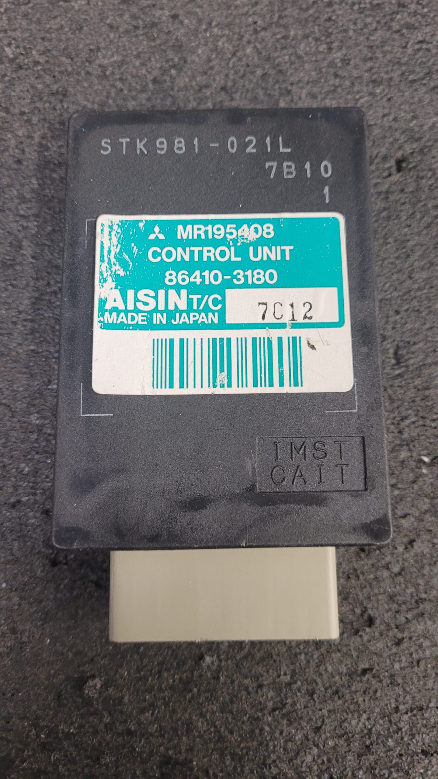
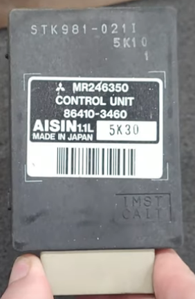
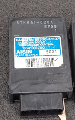
Mitsubishi Pajero Mini Junior AISIN MR195407 MR195408 and MR246350 Daihatsu 89530-87507 Transmission Control Unit Pinouts, There may be others but these are the ones I see often.
This Page May be a mess till fully updated..

This is a Work in Progress, If anyone has the missing information let me know. (Do you need Your Pajero TCU Serviced Click Here For Info)
Need to do,
Solenoid Activation Per Gear?
Engine Pulse Type Magnetic, Hall, other. Info for Shift Points and Pulse Data.
Speed Pulse Info For Shift Points Is Sensor Inductive or Hall Effect?
Figure out Pin 12
![]()
![]()
Connector A | 12 Pin
O Pin 1 Black/White 1st Shift Solenoid
O Pin 2 Black/Blue 2nd Shift Solenoid
O Pin 3 Blue/White 3rd Shift Solenoid
Pin 4 NC
Pin 5 NC
I Pin 6 Green/White TPS +0.60V to +4V (480 Ohm to 1.3K Ohm)
Pin 7 Red/Green (IGN) 12V DC Ignition On
Pin 8 NC
Pin 9 Black GND
Pin 10 Black GND
Pin 11 NC
*Pin 12 Green/Light Green (5v Unknown Function Possibly The Pressure Relief Valve Input or MAP??) (TPS Power)
Connector B | 16 Pin
Pin 21 N/C
Pin 22 N/C
I Pin 23 Pink Engine Speed “Need Pulse Info” Assume Crank Position Sensor? May be other Source Injection System? From Tachometer to TCU
Pin 25 N/C
Pin 26 N/C
I Pin 27 Yellow/Green 2 Position On Shifter +12V Applied If Selected
I Pin 28 Green/Red D Position On Shifter +12V Applied If Selected
Pin 29 N/C
I Pin 30 Black/Blue Speed Sensor Ground (Hall Square Wave / Inductive?)
O Pin 31 White/Blue Speed Sensor Power (Hall Square Wave / Inductive?)
Pin 32 N/C
Pin 33 N/C
Pin 34 N/C
I Pin 35 Yellow/Red L Position On Shifter +12V Applied If Selected
I Pin 36 Green Black “Brake/Stop” (Unknown Function) or N/C On Most Units
Notes:
“O or I” is Output or Input
Solenoid Resistance 12 Ohm 1 Watt Solenoid’s.
Possible Operation Theory (Soon)
3 Gears, 3 Solenoids.
Gear number 1
- Solenoid 1 on/off
- Solenoid 2 on/off
- Solenoid 3 on/off
Gear number 2
- Solenoid 1 on/off
- Solenoid 2 on/off
- Solenoid 3 on/off
Gear number 3
- Solenoid 1 on/off
- Solenoid 2 on/off
- Solenoid 3 on/off
Someone Sent Me The TCU Info was In Japanese Source Translated to English..
Transmission Spec’s Will Need the Gear Ratio Info
![]()
Operation.
![]()
TCU Pinout
![]()
Wiring (Auto Wiring Diagrams Are Bit Different…)
Page 1
![]()
Page 2
![]()
So to make a test bench Simulator.
3 1W 12Ohm Loads For Solenoids
Switches For Selector
Signal Generator For RPM (Siglent S
Signal For Speed
Vairable PSU +0.60V to +4V for TPS
Last Updated on July 22, 2025 by Steven Rhine