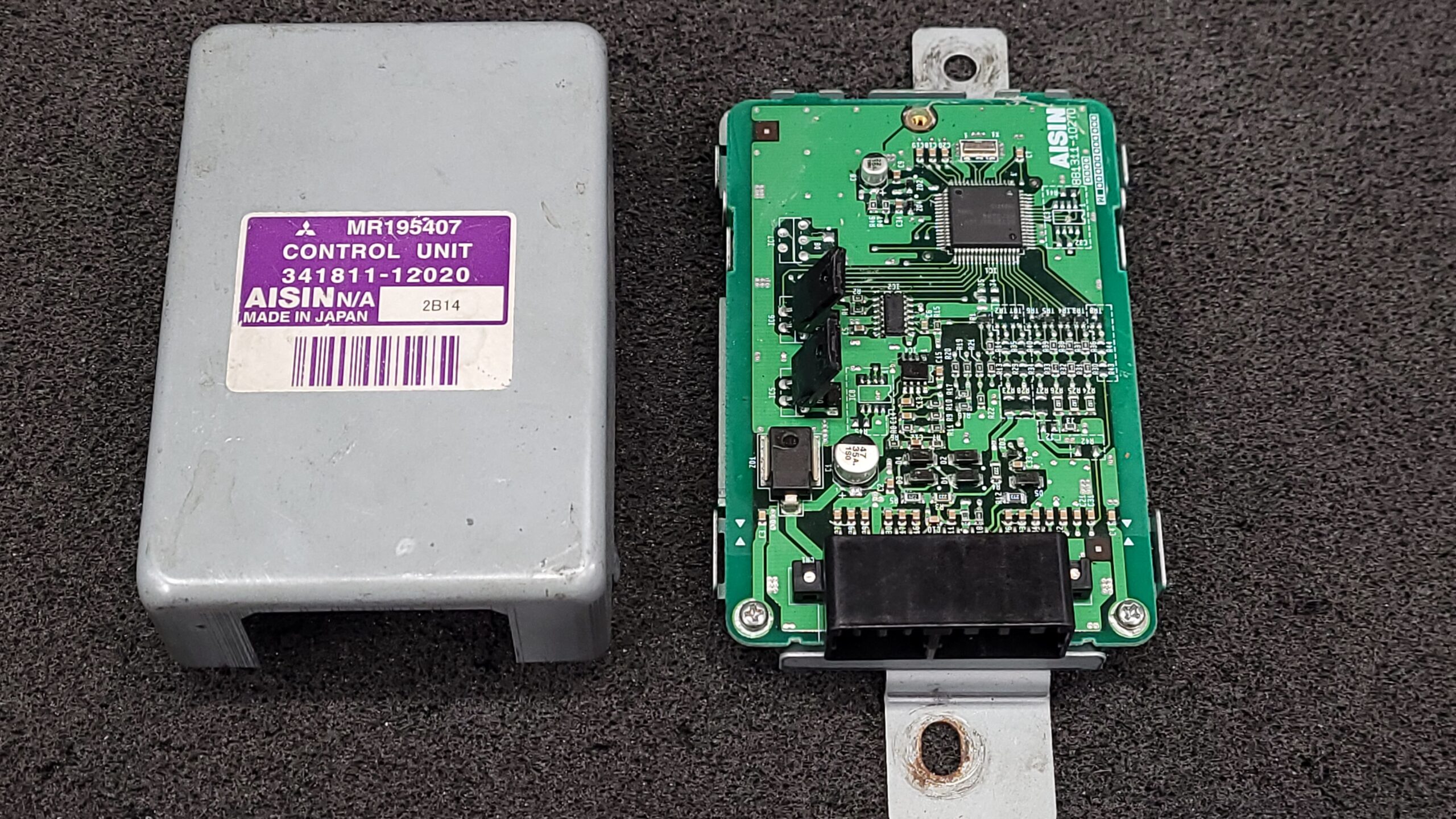
The Pajero “Tin Can” TCUs are generally more reliable than the plastic units and fail far less frequently. In fact, I’ve only encountered a handful of these in need of repair compared to the over 100 of the plastic versions. (This is not info is not complete a work in progress)
This page is intended to provide guidance for individuals who are capable of performing their own diagnostics and repairs. The information is provided as-is. If you are not experienced in electronic repair, circuit tracing, circuit trace repair or soldering surface-mount components, please seek assistance from a qualified professional.
Creating these guides and sharing this information takes time and effort. The best way to support my work is by sending your unit in for repair if it needs service. If you’ve found this information helpful and would like to contribute, please consider making a donation: https://cash.app/$slrhine
Before concluding that the TCU is at fault, always verify that all vehicle sensors are functioning properly in the vehicle.
Yes, I will accept these TCU’s for repair if they have been opened!
Some TCU’s may have component designers labeled differently but they are in the same spot.
Video of a TCU Sent In for Repair, Unit was Not Found to be defective.
General Failure is Electrolytic Capacitors 22uf (C8) and 47uf (C1), the leakage will corrode the traces and surrounding parts, other issues Zener Diodes Shorts, Burnt Transistors and Dead/Shorted MCU (IC1)! I replace C1 with a 47uf 50V will give a longer life.
Below are the test Points for the Mitsubishi Pajero Tin Can TCU’s I know i could work on the flow a little but I many see a half dozen of these a year vs many dozen of the plastic ones.
1st of all check the tcu’s Current Draw this will tell you a lot and save you a lot of time.
When Powered up with a Precision Current Limited Power Supply (Siglent SPS3303X-e) at 14VDC Current limit to .200ma + to Pin 7 Ground to Pins 9 and 10 on 12 Pin Connector.
You will see a Current Draw at .045-.047ma briefly then will drop to .020- .024ma this is normal operation generally nothing is wrong with the TCU. If the unit stays .030ma or higher there are issues generally shorted / leaky caps if Current is in the 100ma or higher its generally a shorted zener diods/transiostors/mcu. (On the plastic TCU’s this is not the case as the issues are in a different area different circuit design)
You will need sharp probes to poke thru the conformal coating to make contact with the component leads.
Check for 4.00 mhz on the the Crystal “X1” near the Microcontroller I use a (Siglent SDS 2104X Plus) oscilloscope but use whats you have if this is Missing MCU is Not starting Check for Voltages

Votlages:
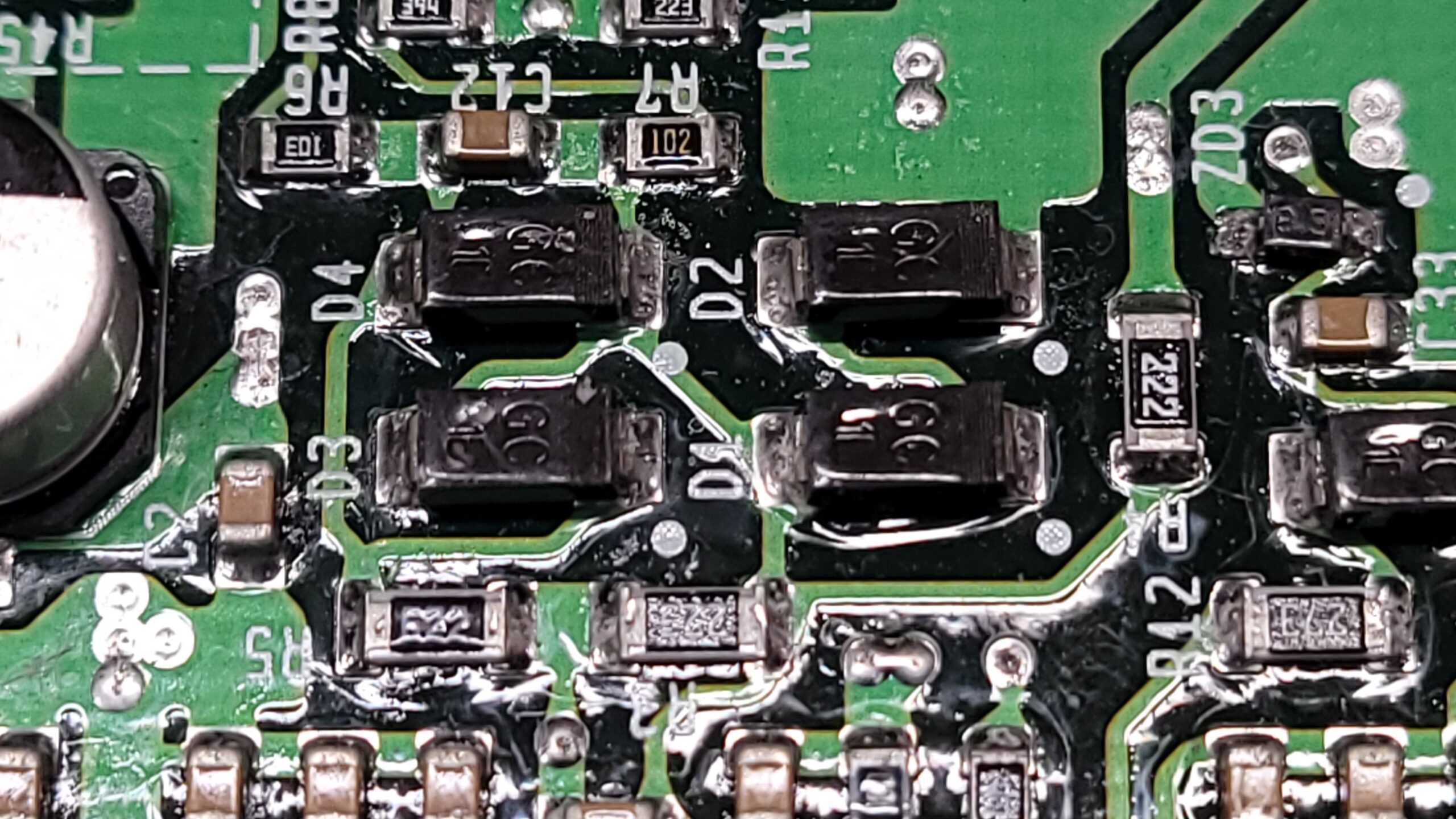
ZD4 3V (MCU Voltage) If Missing replace Caps and check ZD4 Zener Diode 5.1V 400mw SOD323 (Replace with 500mw)
ZD2 5V If Missing Check For Short on Transistors, If no short replace Capacitor and ZD2 Zener Diode 6.8V 400mw SOD323

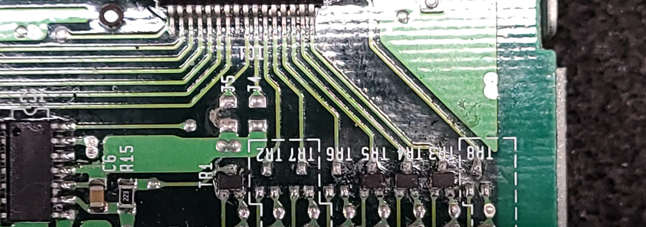
TR1,2,3, 4, 5 & 7 +5VDC Normal if Missing Check Short Replace Shorted Transistor.
If all of the above is working and MCU is not Starting the MCU is Dead Replace TCU but do not discard it!! (I am working on a replacement MCU)
Also, Inspect the MCU for Broken Solder Connections, sometimes you need to clean off the conformal coating first as it can be really thick. I inspect the pins under Microscope but you can do it with a strong magnifying lamp if you have good eyes sometimes crack connections are hard to spot.
Check, Shift Solenoid Switches Pin 1 and 2 on Connector A default is “both on + 12V” if less then 12V Check Caps, Diodes, Broken Connection, and 5151s I have not seen a 5151S Fail yet generally its the Diode that shorts to ground.
Continuity Check
![]()
![]()
Connector A | 12 Pin
O Pin 1 Black/White 1st Shift Solenoid Solenoid +12V IC5 Pin 3 12V If Missing Check Continuity, Diode D6, and 5151S
O Pin 2 Black/Blue 2nd Shift Solenoid Solenoid +12V IC6 Pin 3 12V If Missing Check Continuity, Diode D7, and 5151S.

5151S Pin 1 Ground, Pin 3 12V, Pin 5 14v ( If 14V is Low or Missing Check C1 or ZD1)

Pin 3 NC (3 Speed Variants Will Have IC7 D8 Populated)
Pin 4 NC
Pin 5 NC
I Pin 6 Green/White TPS (R16 Check if Open) & C20 For Short
Pin 7 Red/Green (IGN) 12V DC Ignition On
Pin 8 NC
Pin 9 Black GND
Pin 10 Black GND
Pin 11 NC
*Pin 12 Green/Light Green (Map/TPS Power) (R16 Check if Open) and C18 for Short
Connector B | 16 Pin
Pin 21 N/C
Pin 22 N/C
I Pin 23 Pink Engine Speed R13, TR1, ZD3 Check ZD3 (Zener Diode 6.8V 400mw SOD323) will generally be Burnt if it has failed have not seen one failed that was not burnt!
Pin 25 N/C
Pin 26 N/C
I Pin 27 Yellow/Green 2 Position On Shifter +12V Applied If Selected Check R25 and TR4
I Pin 28 Green/Red D Position On Shifter +12V Applied If Selected Check R26 and TR5
Pin 29 N/C
I Pin 30 Black/Blue Speed Sensor Ground (Hall Square Wave / Inductive?) Check Diodes
O Pin 31 White/Blue Speed Sensor Power (Hall Square Wave / Inductive?) Check Diodes
Check R3,4,5 for Open.
Pin 32 N/C
Pin 33 N/C
Pin 34 N/C
I Pin 35 Yellow/Red L Position On Shifter +12V Applied If Selected Check R24 TR3
I Pin 36 N/C
The only thing I am unable to check is the MCU Program Code.
If anyone has an Oscilloscope and would like to log sensor data and shift points it would be greatly appreciated.
I Also Need the Resistance of the Shift Solenoids.
With this info requested I can use a DC Load and Wave for generators and Simulate the vehicle in driving conditions. I could even make a small plug in tester that would auto test the TCU to say if it is good or bad or whats broken.
Last Updated on October 15, 2025 by Steven Rhine