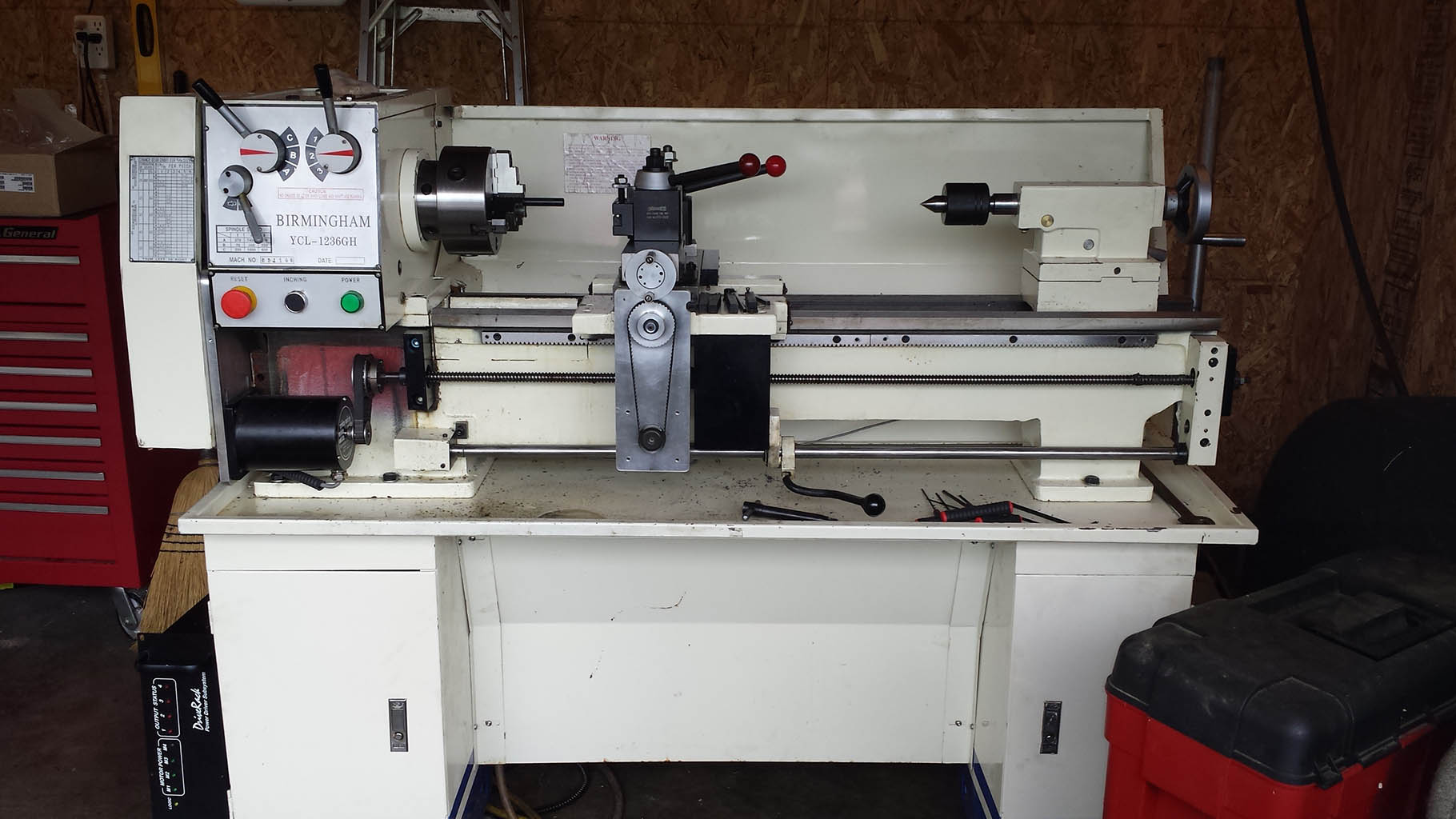
CNC Lathe V 3.0….. In the works… They Say the 3rd time’s a Charm Lets See!
On this Revision I am Going to be using 3 Phase Steppers… & Tormach Path Pilot V2.0.0 I was able to Obtain a Tormach Slant Pro Main Board should be arriving 12-15-2017 so there should be very little configuration with Path Pilot Prob just the INI Files.
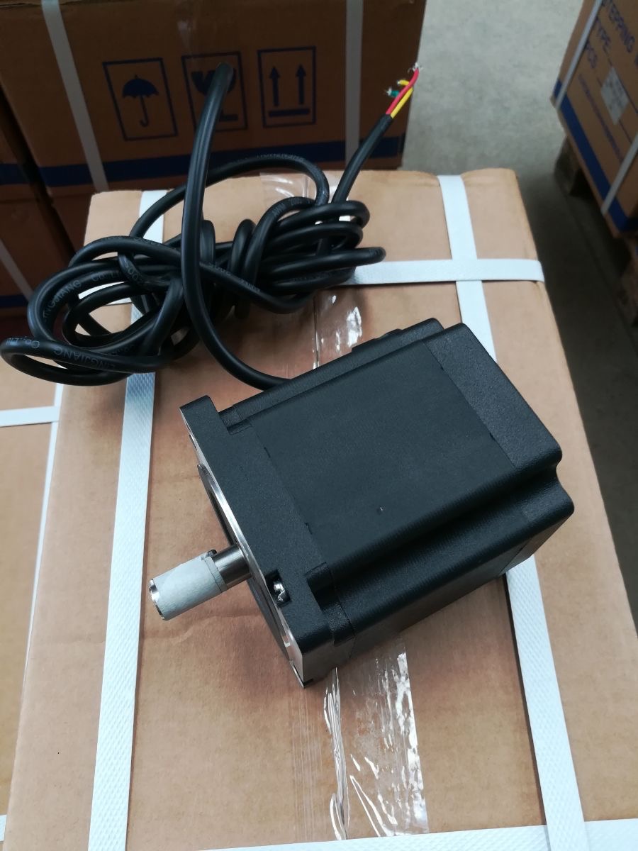
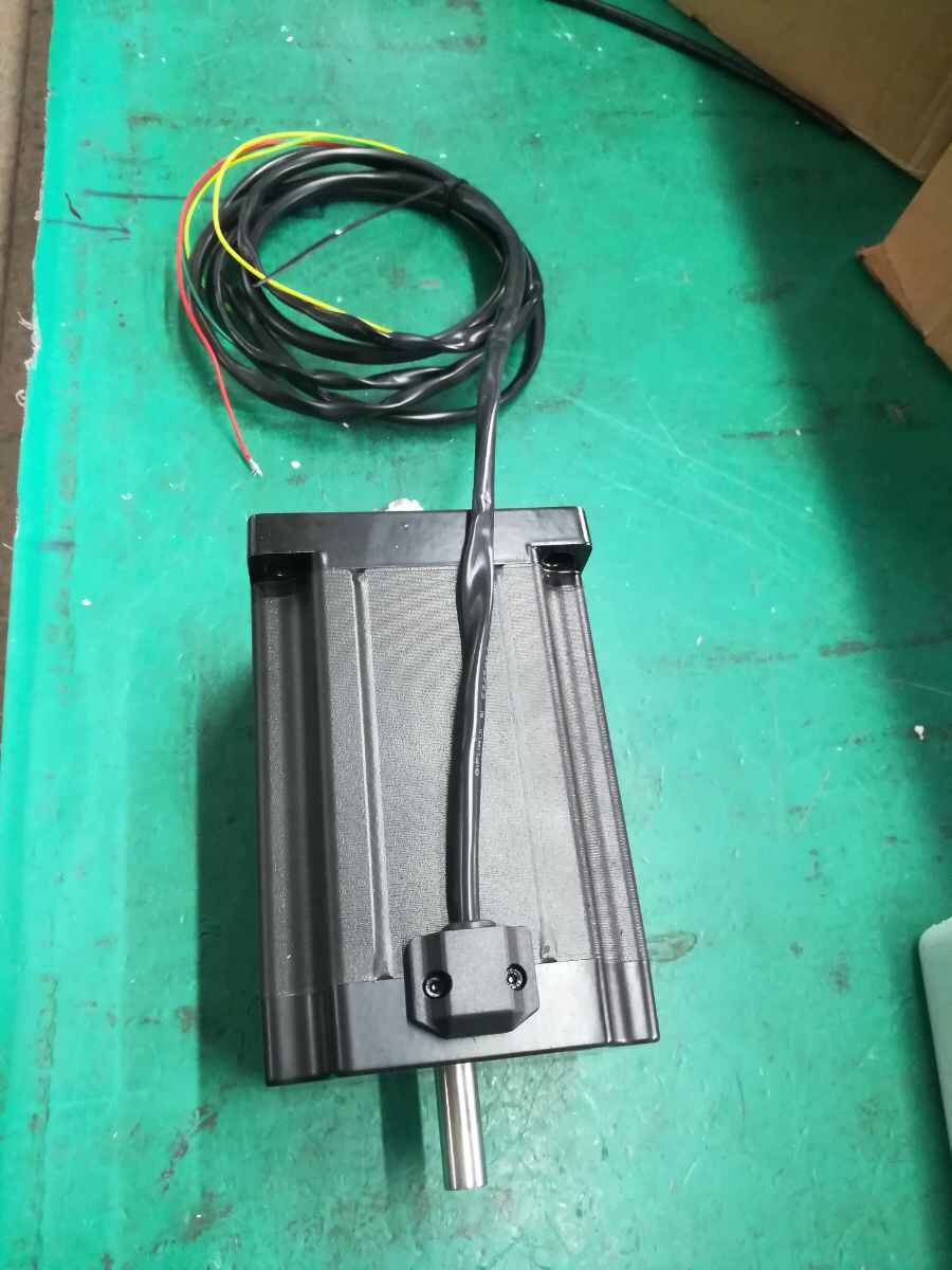
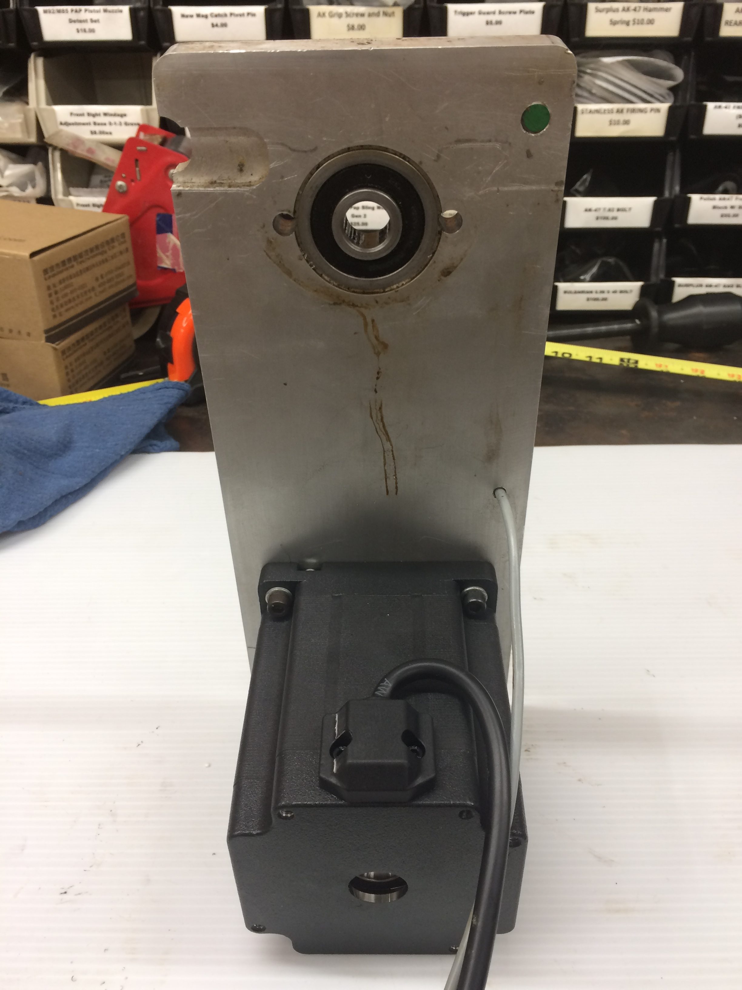
Had to have these Motors Custom Made… In China! Ordered them November 27th 2017 form Changzhou Chuangyi Electrical Appliance Co. Ltd. Photos they sent me of completed Product.
Nema 34 (Left) & Nema 42 Dual Shaft (Right) 3 Phase for the X & z Axis
Download Nema 34 Motor Drawing
Download Nema 42 Motor Drawing
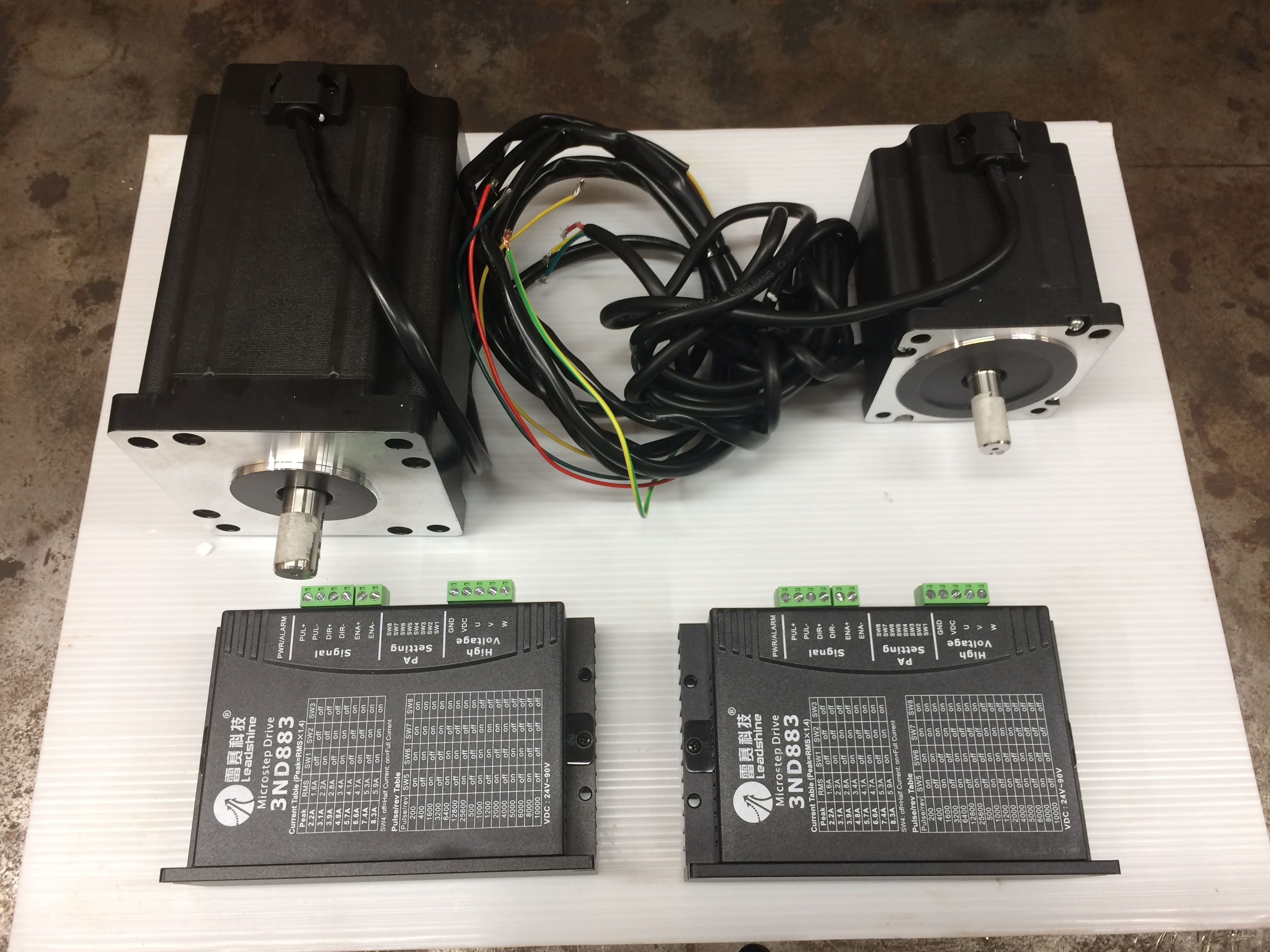
I will be using Leadshine 3ND883 3 Phase Drives
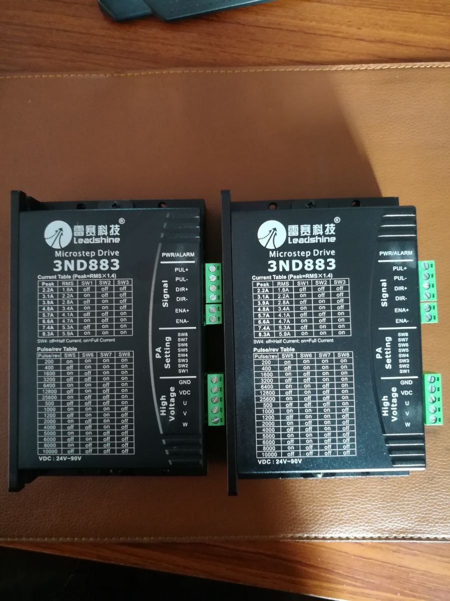
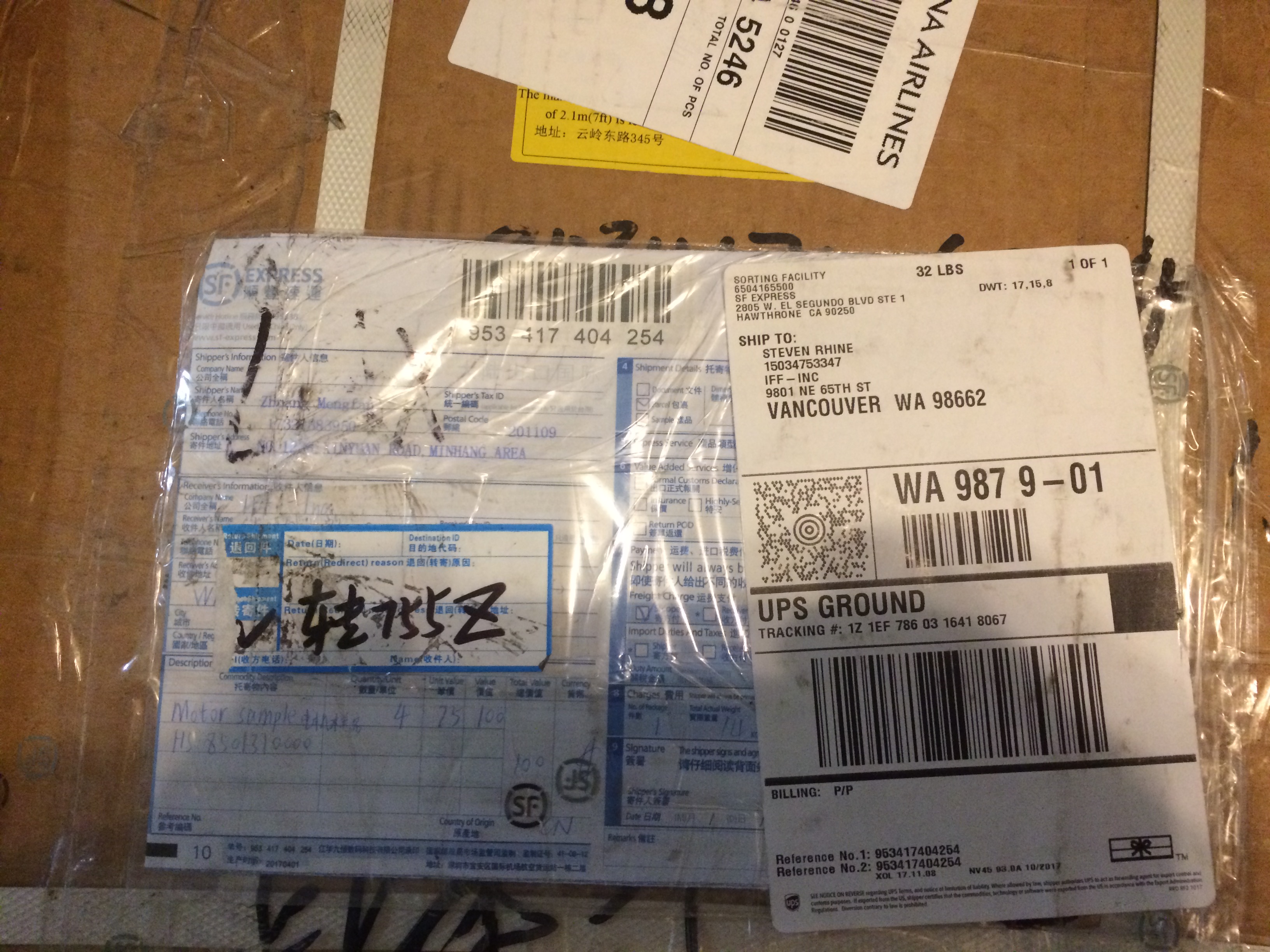
Mail Call 12-11-2017 Motors & Drives Arrived!!!
Unboxing Video…. Of the Motors>>>> Christmas Came Early!!!
Looks Like it all made it from China to USA all Safe… Will Be Testing This Week end If I have Time.
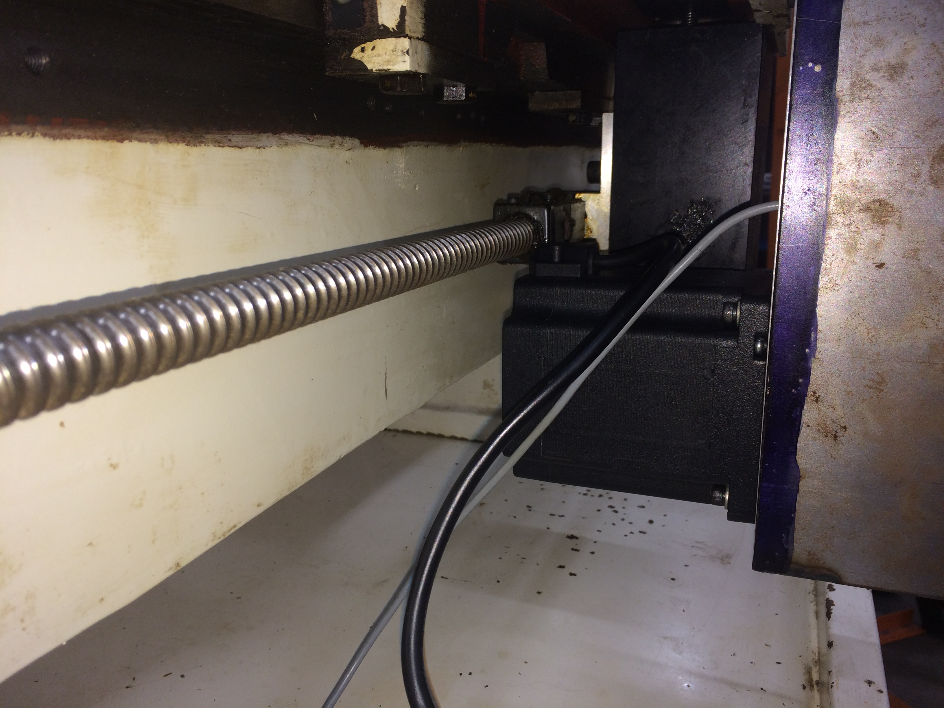
Let the Swap Over Start…
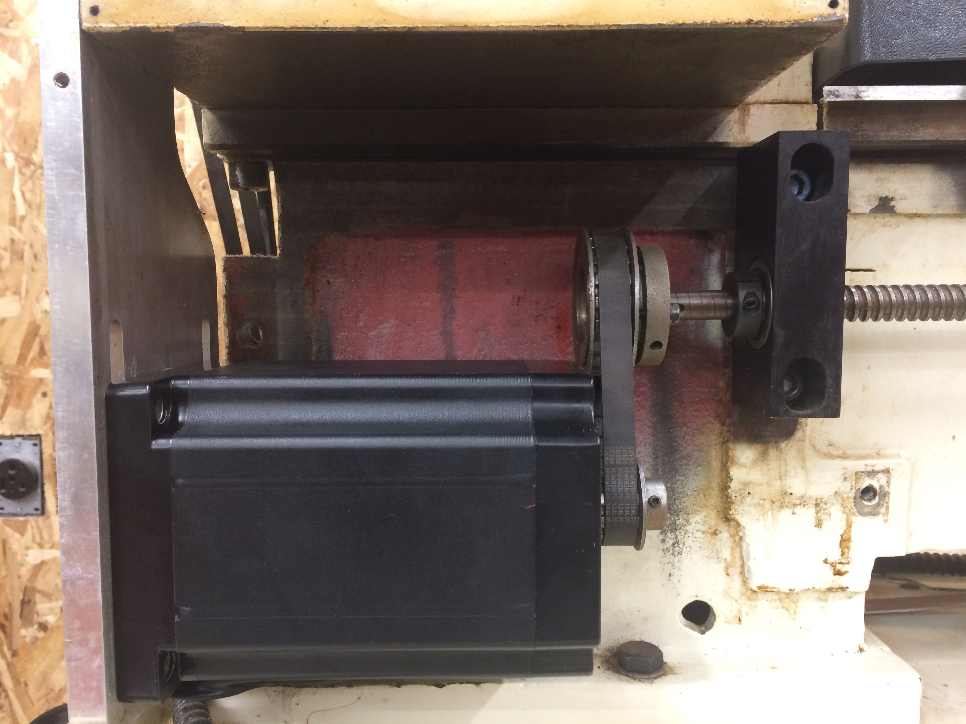
Z Axis is a Perfect Fit….
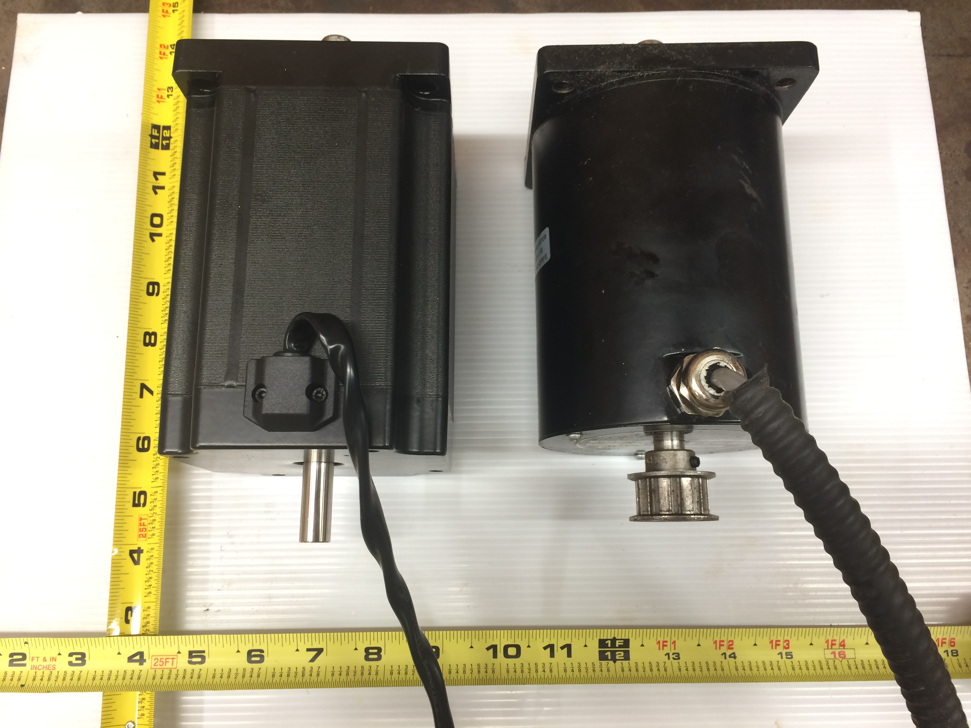
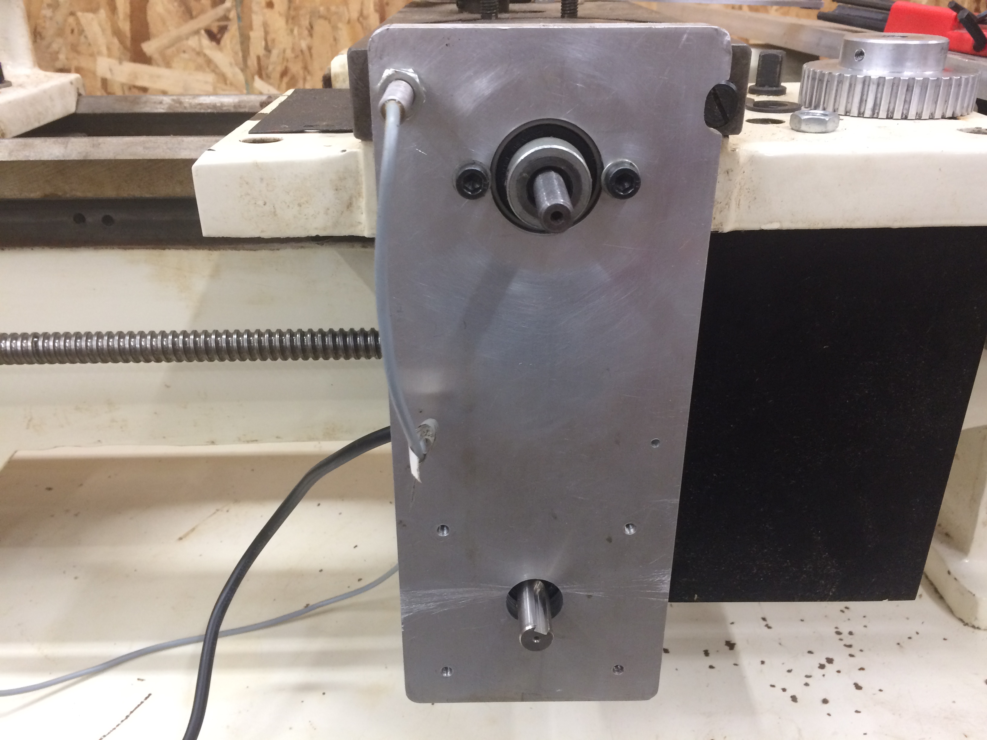
X Axis…. My Bad Have to Oder a new Pulley because the shaft is larger on the X-Axis.

Achieving 240IPM… on the Z axis! Nice a Quiet and Super Smooth Compared to 2 Phase Steppers.
Homing the X Axis…
Mail Call…. 12/17/2017
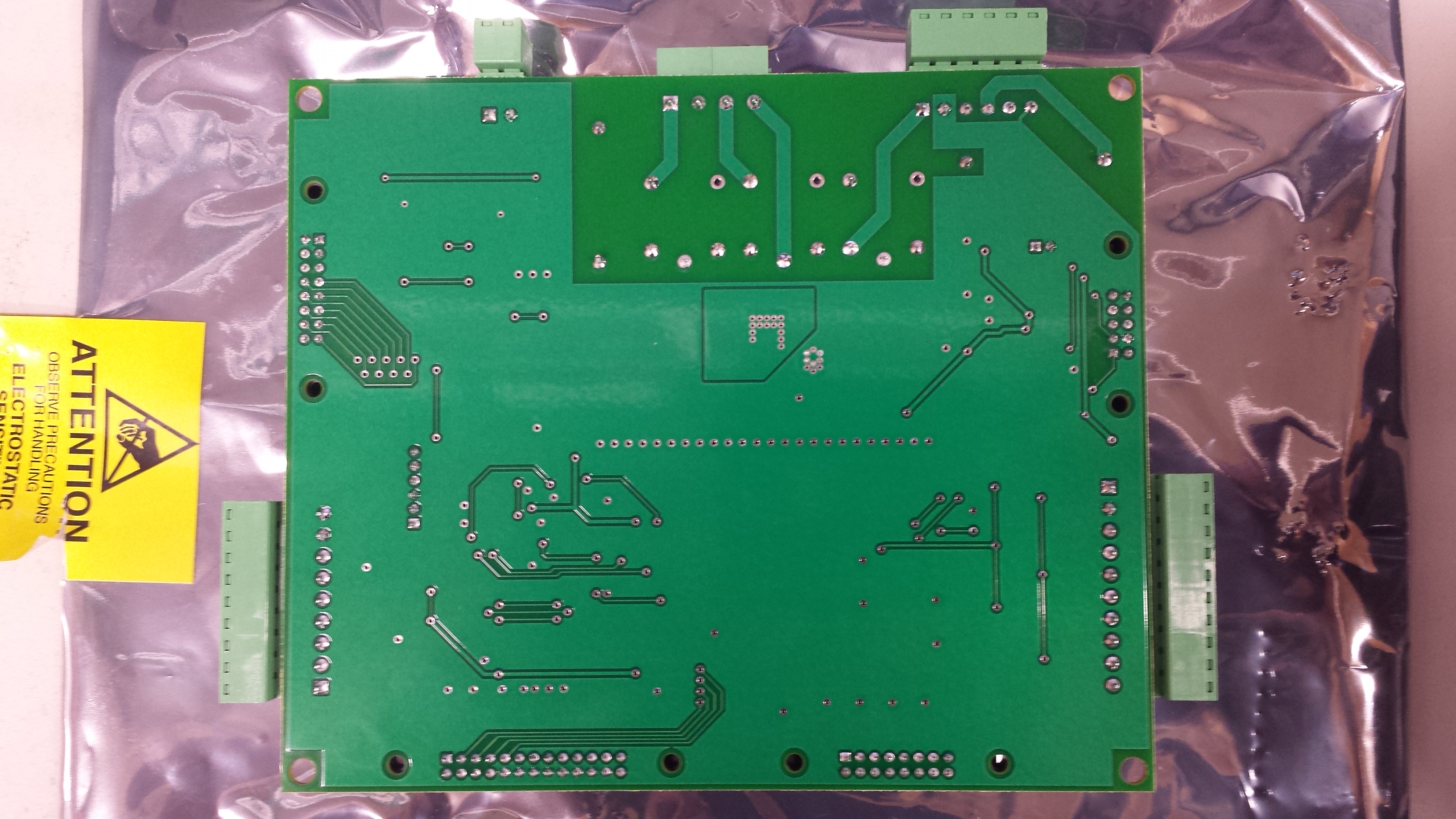
I know it is a Bit late Arrived Friday Evening 12/15… What we have here is the The Elusive Tormach Lathe Control Board… (**Note: Tormach Will Not Sell These to non Slant Pro Lathe Owners**) I was lucky and able to obtain one.

The Tormach 15L Slant-Pro Lathe Manual has most all the Pinouts except for IDC Headers J2, J3 and J6 Ready for a Probing…

We Will Ignore J2 Right Now That Is For The Turret Tool Changer System Not Going to Use Yet?, My Priority Was J6 That is Where the Stepper Drivers Connect After Some Simple Tracing on J6 It Resulted The Following…
J6 IDC Connector Pins
“May Be Useful If a Tormach Owner Ever Need to Replace a Tormach Drive That Uses an IDC Connector not Screw Terminals”
X Dir Pin 2
X Step Pin 3
X 5vdc Pin 4
Z Dir Pin 8
Z Step Pin 9
Z 5vdc Pin 10
After Some Simple Edits to the Lathe INI File… Basics that should not need changed, Machine Limits, & Motor/Screw/Step Data… It Runs! If just Testing you will See JP1 it is a jumper to disable limit switches. I did test it with a mechanical limit switch all is good… Not able to test with proximity sensors as i have PNP and need to use NPN.
Now on to IDC Connector J3 machine LED’s and Accessory Port.
Accessory Port J3
Pin 1 12V
Pin 2 5V
Pin 3 Input
Pin 4 Ground
Machine LED’s
System:
Pin 5 +5Vdc
Pin 6 Grnd
Computer:
Pin 7 +5Vdc
Pin 8 Grnd
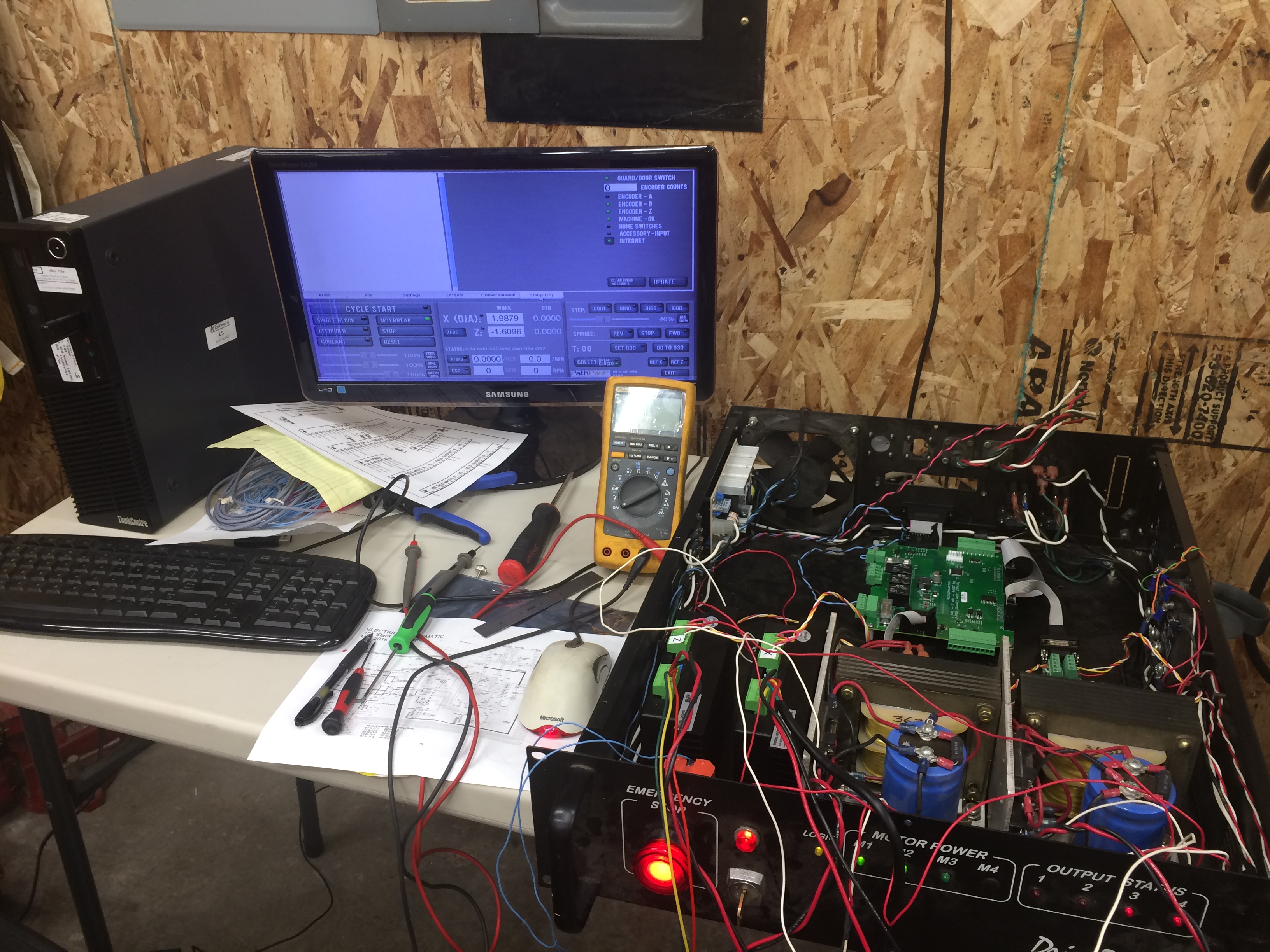
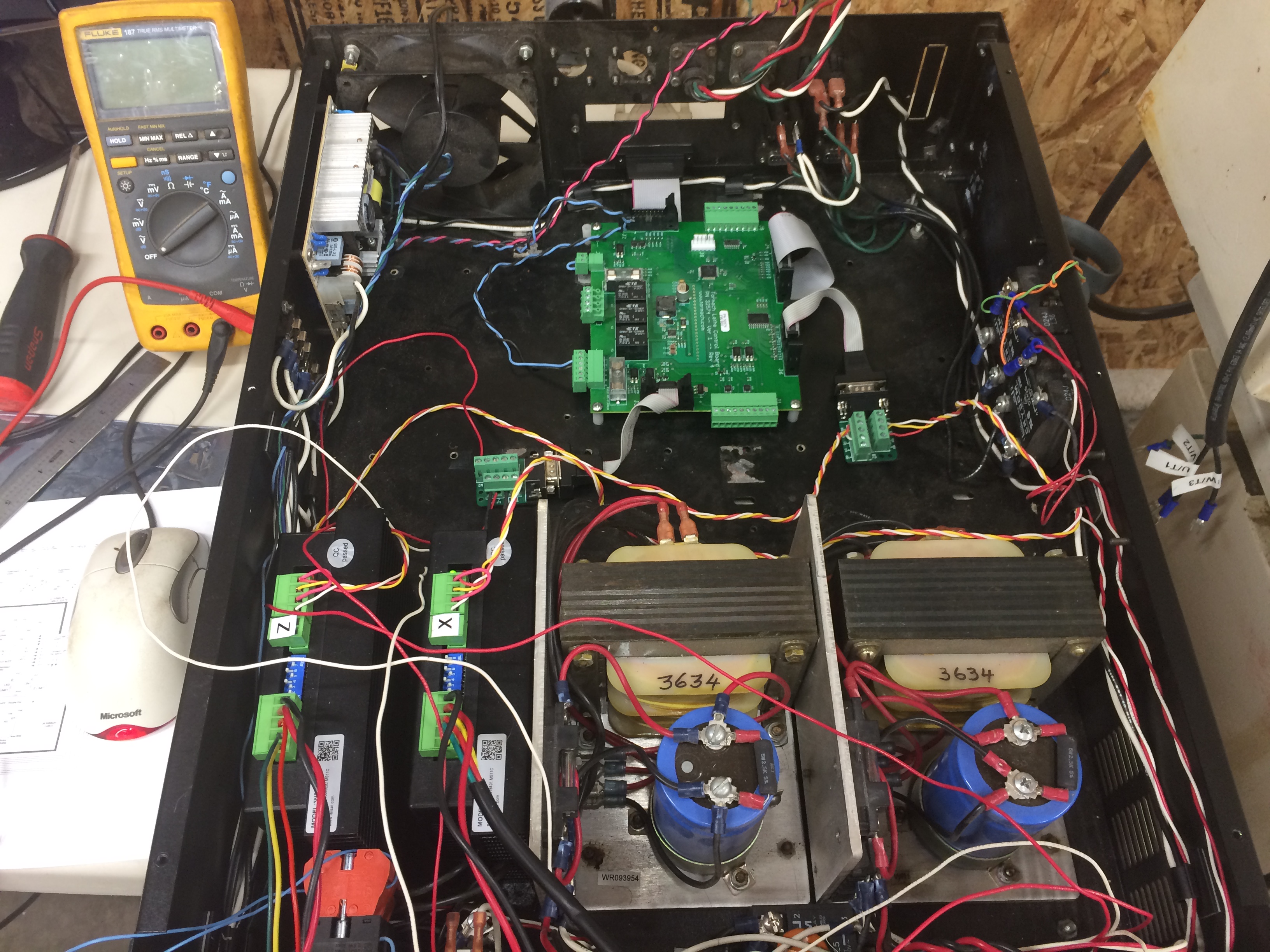
It’s a Mess But its Working… Maybe I can get to wiring the VFD and Check the Spindle… before I have to halt things for a couple weeks.
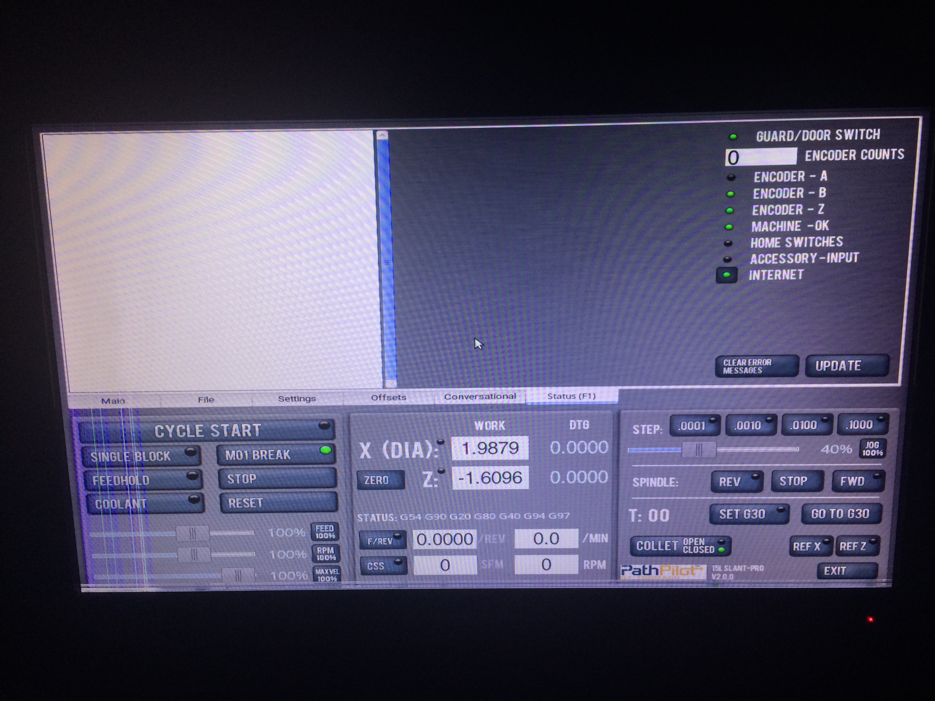
Path Pilot 2.0 All Green…
Next project is the Spindle…
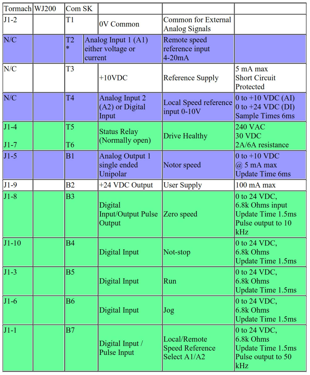
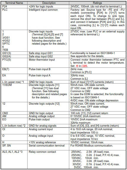
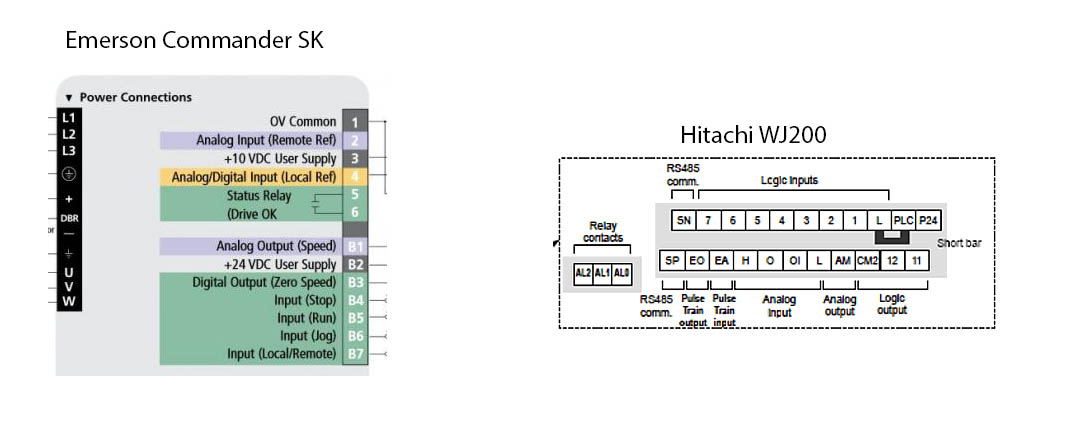
I will Not be using the Emerson Commander SK VFD that Tormach uses it just went Obsolete in October and was replaced by the Emerson Unidrive M Series. I will using the Hitachi WJ200-022SF VFD I already have on hand. Here are some of the Pins and Functions/Terminal Connections For For The Emerson Commander SK And the Hitachi WJ200 VFD
Terminals Side By Side..
As of 12-30-2017 No real work Completed Due to Surgical Recovery.
Update 01-18-2018 I had to put a Call Out for help on the VFD Settings..
Thank To rdsi on CNCzone he had logged the Emerson VFD Settings that Tormach Uses.. See This XLS File!
Still Stuck On a The VFD Settings… I Currently Get Movement FWD and Reverse but only 5HZ Variable Speed.
Emerson Commander SK = Hitachi WJ200-022SF
T1 = L Lower
T5 & T6 = N/A (This is an E=Stop if Closed Prob Will set it to Normally Open Alarm Relay AL0-AL1 on the Hitachi.)
B1 = ? See Below
B2 = P24
B3 = ? See Below
B4 = N/A (Drive Enable Tied to B2 24V Pins 9 & 10 on BOB)
B5 = 1 (Forward)
B6 = 2 (Reverse)
B7 = ? See Below (Solved Connect to EA) Set WJ200 A001 Frequency Source to 06 Set P055 Pulse Train Freq. Scale.
From the Emerson SK Manual
B1 Analog Voltage Output – Motor speed
Voltage Output 0 to +10V
Scaling 0V represents 0Hz/rpm output +10V represents the value in Pr 02 Maximum set speed
Maximum output current 5mA
Resolution 0.1%
B1 Tormach Setting
A ,Voltage proportional to output current. Again not sure how to translate that to Hitachi WJ200 or Hookup Point.
B3 Digital Output – Zero Speed (or Digital Input)
Voltage Range 0 to +24V
Maximum Output Current 50mA at +24V (current source)
B3 Function Tormach Settings:
N=0, Zero Speed ??? How does that Translate to Hitachi WJ200.
Assume it will be function C Group, 22, = Output 12, Option 21 ZS: 0 Hz detection signal.
B7 Digital Input – Local/Remote Speed Reference
Logic Positive
Voltage range 0 to +24V
Nominal threshold voltage +10V
B7 Function Tormach Settings
Fr, Frequency Input.
How to translate that to Hitachi WJ200 Using A001 Option 6 Pulse Train Setting and EA On Hitachi
May Be Other Settings… I am missing I am not an expert at the VFD’s and the Manuals are hundreds of pages and read like 1980’s Electronics Instructions each calling a function something else.
Using Hitachi’s ProDriveNext Dose Simplify the Settings a bit. I will upload my Drive Configuration File AFS file for WJ200(V.2.x) once it is figured out fully.
Here is My Original Drive Configuration File. (Right Click Save As)
01/19/18
Leaving B1 & B3 Disconnected, Just going off the frequency pulse train input. By Default it was only going up to 8khz on the VFD at max RPM setting very slow.. So reading thru the 400 pages and Changing Setting P055 Pulse Train Freq. Scale from Default 25khz to around 12.5khz gets me a very active spindle. Not accurate at all but getting somewhere with the spindle will require some fine tuning prob both the VFD and PathPilot maybe even a pulley ratio change on the machine.
But it is Alive Again…
01/29/18
Making Lots of Progress… In the lathe INI Spindle LO_SCALE = 4.625 I get All the way up to 2,500RPM but over 120HZ on the motor.
Still have a few test settings to do with the VFD and still a have not traced out B1/J1-5 or B3/J1-8, I cannot see how Tormach is using them on the board since they are using a frequency pulse for the speed. It may have something else to do with spindle at speed that’s not implemented or ???
07/19-20/18
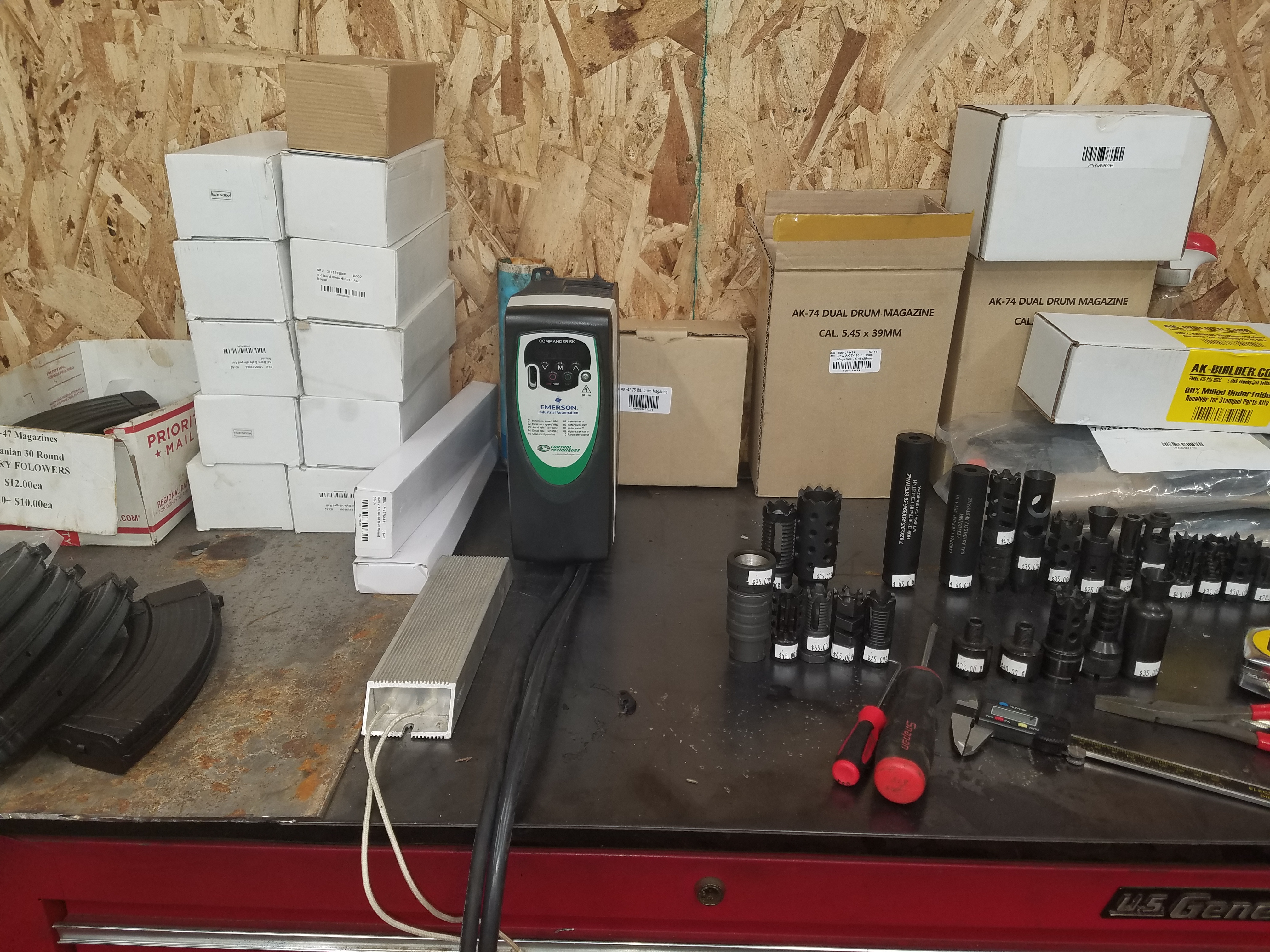
It has Been a Few Months I have been Busy with the Shop Remodel and Life. But I obtained a Emerson Commander SK SKCD200220 VFD it is the same as the Tormach but 2.2KW Not 1.5KW. It looks like I Had better luck with the Hitachi. I Downloaded the CT-Soft to program to edit the advanced drive Parameters. The short list provided in the Excel sheet (Above) is missing some of the advanced stuff. I forgot who I lent my USB to RS485 cable to couple years back but scrounging through boxes and such I did find 3 usb to RS232 adapters (of no use here).. So a new USB to RS485 adapter is on order from amazon be here on Sunday the 22nd and with my luck recently it will arrive and I will find my other one a week or so later.
Under manual control this Emerson VFD is quiet (No Sequel) compared to the Hitachi VFD.
But the RJ45 Wiring is Pins
pin 2 = Orange = Rx
pin 7 = Brown/White = Tx
pin 3 = Green/White = GND
08/12/18
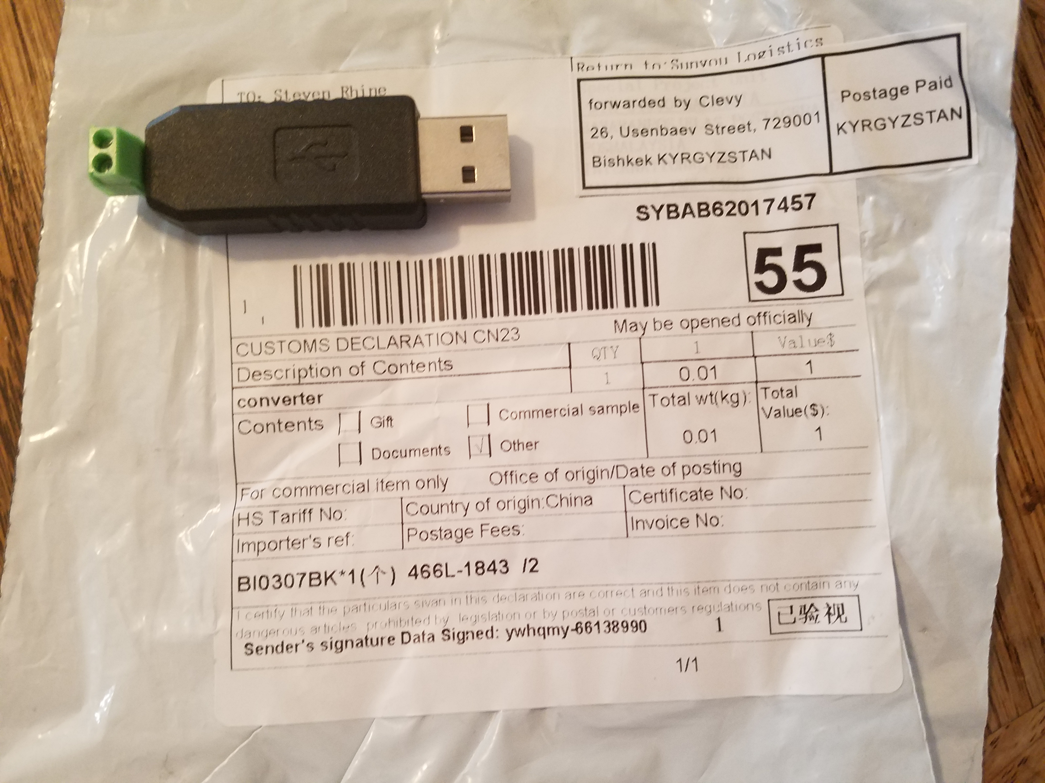
Received a China Made $0.99 Shipped USB to RS485 Adapter Wow Works Just as Good as The one From Amazon Above Using Pins 2 and 7 for Ground I did solder ground to the usb shield. Packing could have been better just tossed in a bad but for .99 no complaints I will add it to the drawer of adapters! If you own a tormach and have one of these Emerson Drives best to get a RS485 adapter back it up as they are a common failure point from what i read on the forums and are obsolete / discontinued and have been replaced by a newer model # but NOS and good Used Drives can be found on Fee-bay for about $100.
Tormach PCNC 1100 VFD Parameter File For Use With CTSoft. (08/10/2018 Read My VFD Enabled And Running)
Tormach Slant Pro VFD Parameter File For Use With CTSoft Corrected Parameter 01.14 Changed From “Pad” to “Pr”. “Original .Par File As Donated from a LCNC Forums Member”
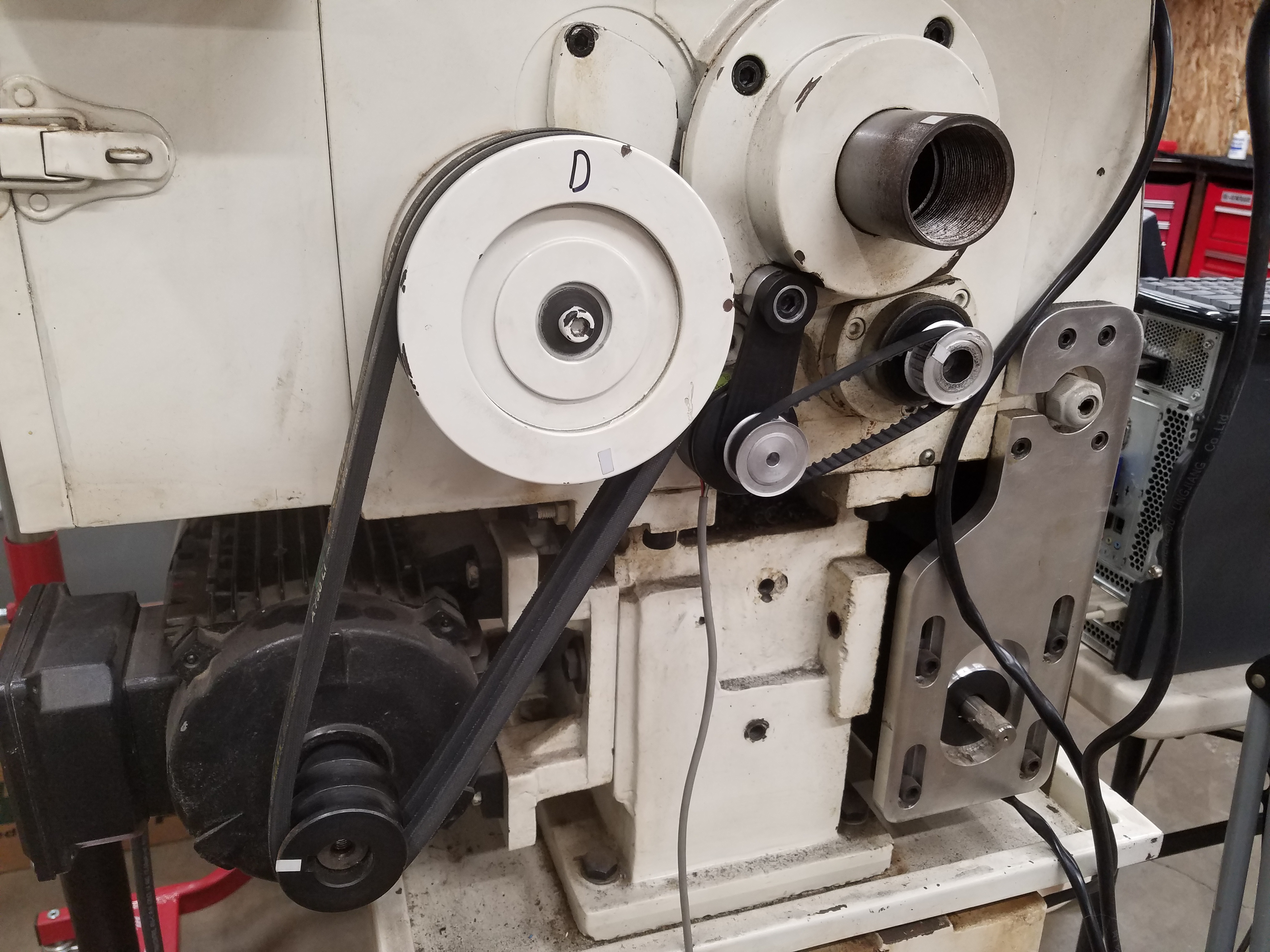
I have to change the Pulleys on my Head Stock to achieve the 2500 RPM at the Spindle at a Decent Motor Speed without it having issues. Prob Go down 1″ on the Driven Pulley (D) and Maybe up 1″ on the Drive Pulley.
Sorry Not many Updates.. Nearly Complete.
Last Updated on October 17, 2021 by Steven Rhine
[…] to another version and with a Tormach Slant Pro Lathe Controller and path pilot 2.0 […]