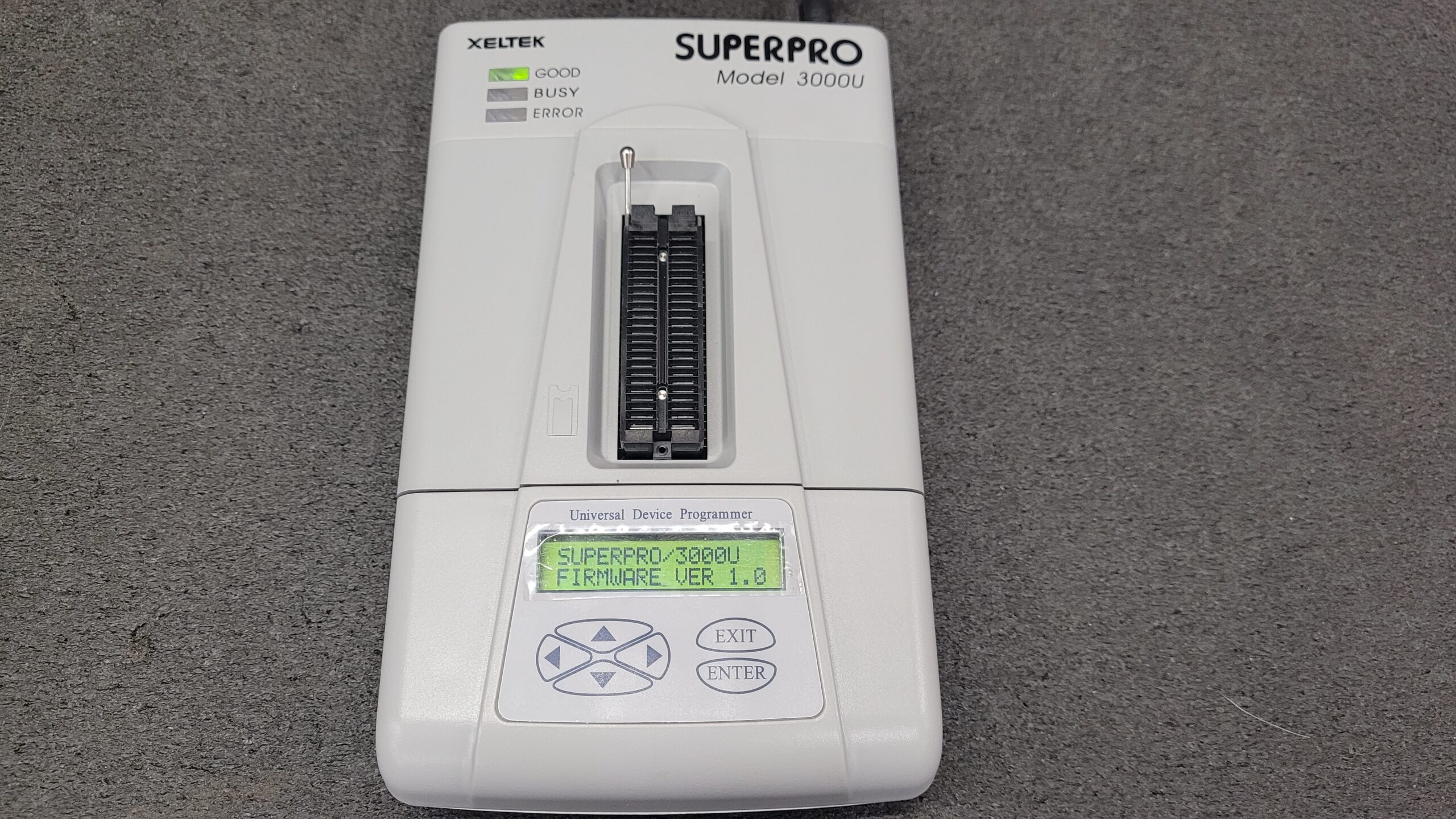
Xeltek SuperPro 3000U Programmer Calibration Procedure.
Common Xeltek Superpro 3000U Issues: Leaking Electrolytic Capacitors & Faulty MC34063 1.5 to 40v Inverter Regulators.
See My Full Xeltek Superpro 3000U Teardown (I Lost 1/2 the video and all audio so I have to redo it oops)
These programmers are pushing 20 years old and showing their age. I decided to open mine up for inspection since it does more sitting in a cabinet than earning now days. I checked my electrolytic capacitors in-curcit with an ESR meter they check acceptable no electrolytic leakage was seen.
Regardless if the capacitors read within acceptable limits after 18 or so years all the Electrolytic capacitors should be replaced. So, Yes! I will be replacing them with some quality Rubycon and Nichicon caps before the dreaded leakage starts and pcb damage occurs. A List of the electrolytic capacitors is provided at the bottom of the post as is a Mouser Project List. Overall parts cost for capacitors is about $6.00 + shipping. A Small price to pay for preventative maintenance.
Following any repairs you need to check calibration more then likely you will need to calibrate the programmer.
Now on to the Calibration Procedure.
Tools Required For Calibration Procedure
#1 Phillips Screw Driver
2mm non metallic pot adjust driver (Ceramic)
Quality Digital Multi Meter 4.5 to 6.5 Digit Resolution (Fluke, Siglent, BK, Agilent, Etc)
ESR Meter to Check Capacitors
(If you Elect to or have to change the electrolytic capacitors out or have a faulty 1.5 to 40v inverter regulator the appropriate soldering/desoldering equipment, flux and solder is required)
If you do not feel conformable doing this contact me on the Xeltek Superpro User Group I can do it for you for a small fee + parts and shipping.
1) Download and install the test software for the Superpro 3000U from Xeltek (Here) or (Archive)
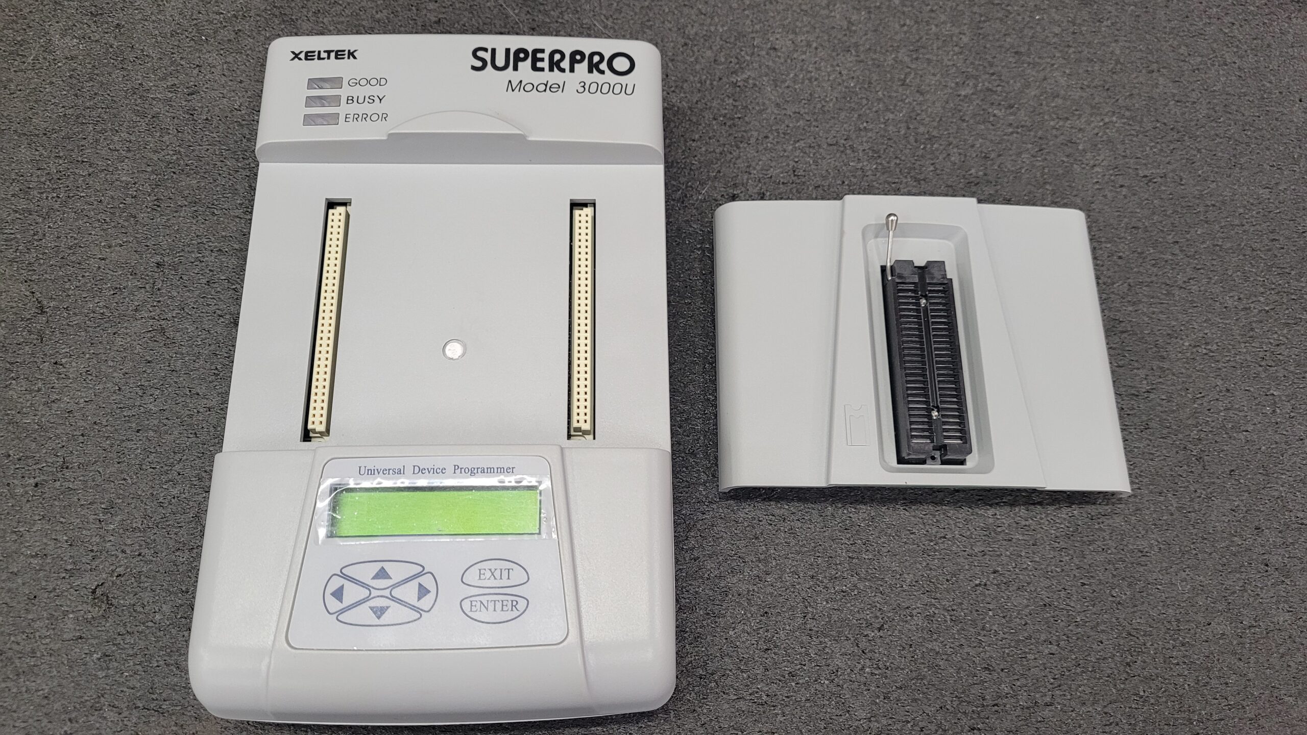
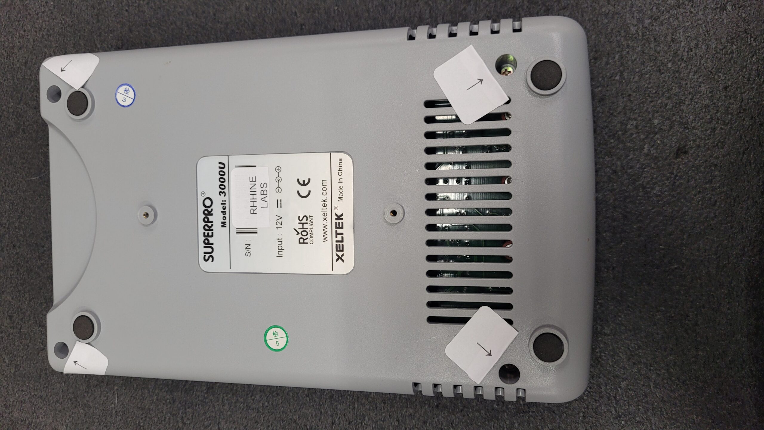
2) Open the Xeltek Superpro 3000U by removing the socket adapter on the top of the unit and the four screws on the bottom of the unit.
When lifting the top off do not loose the 4 standoffs and Carefully remove the power switch from the top half of the case so that the top half of the case can be folded forward with all of the cables still connected.
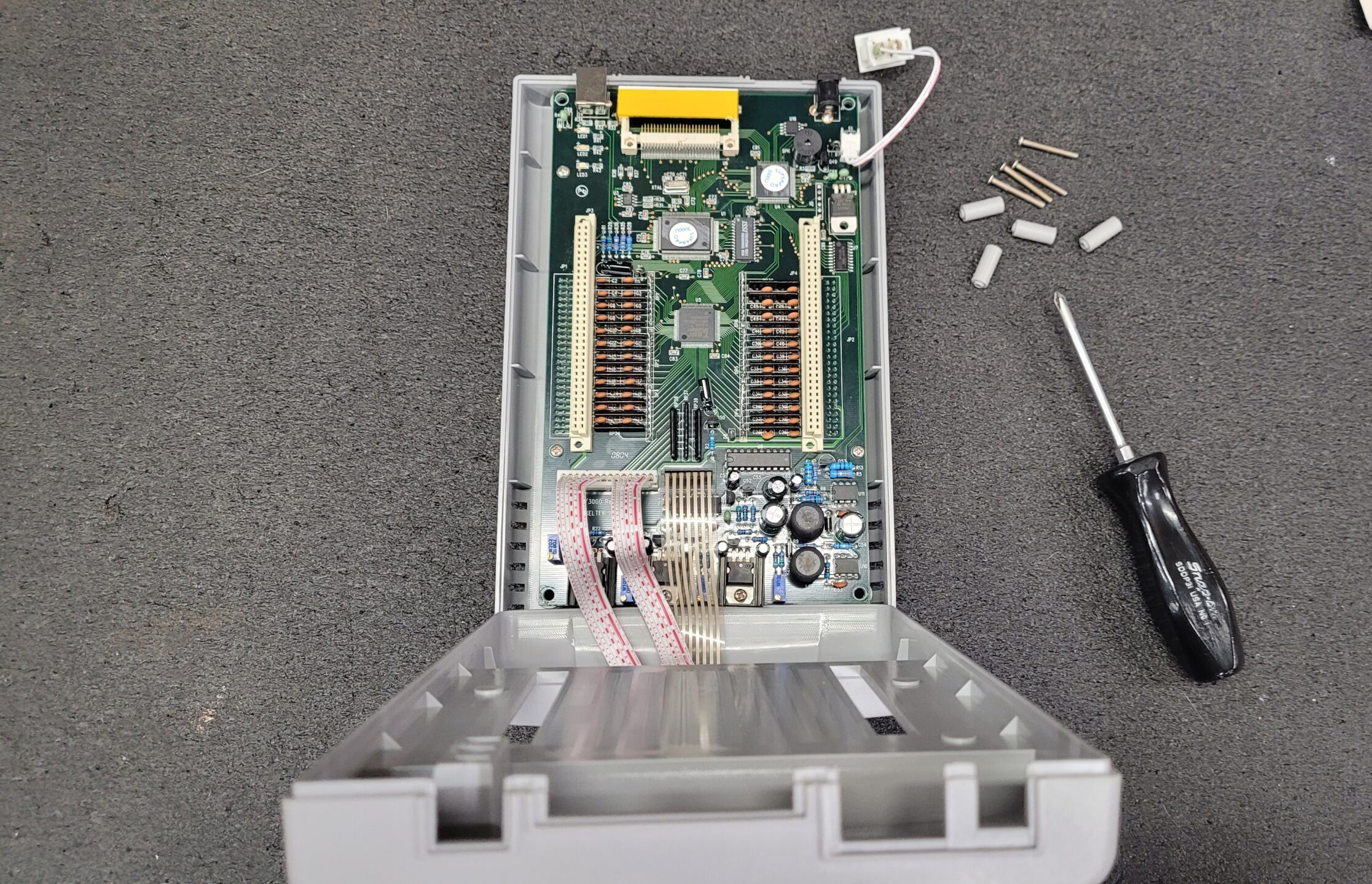
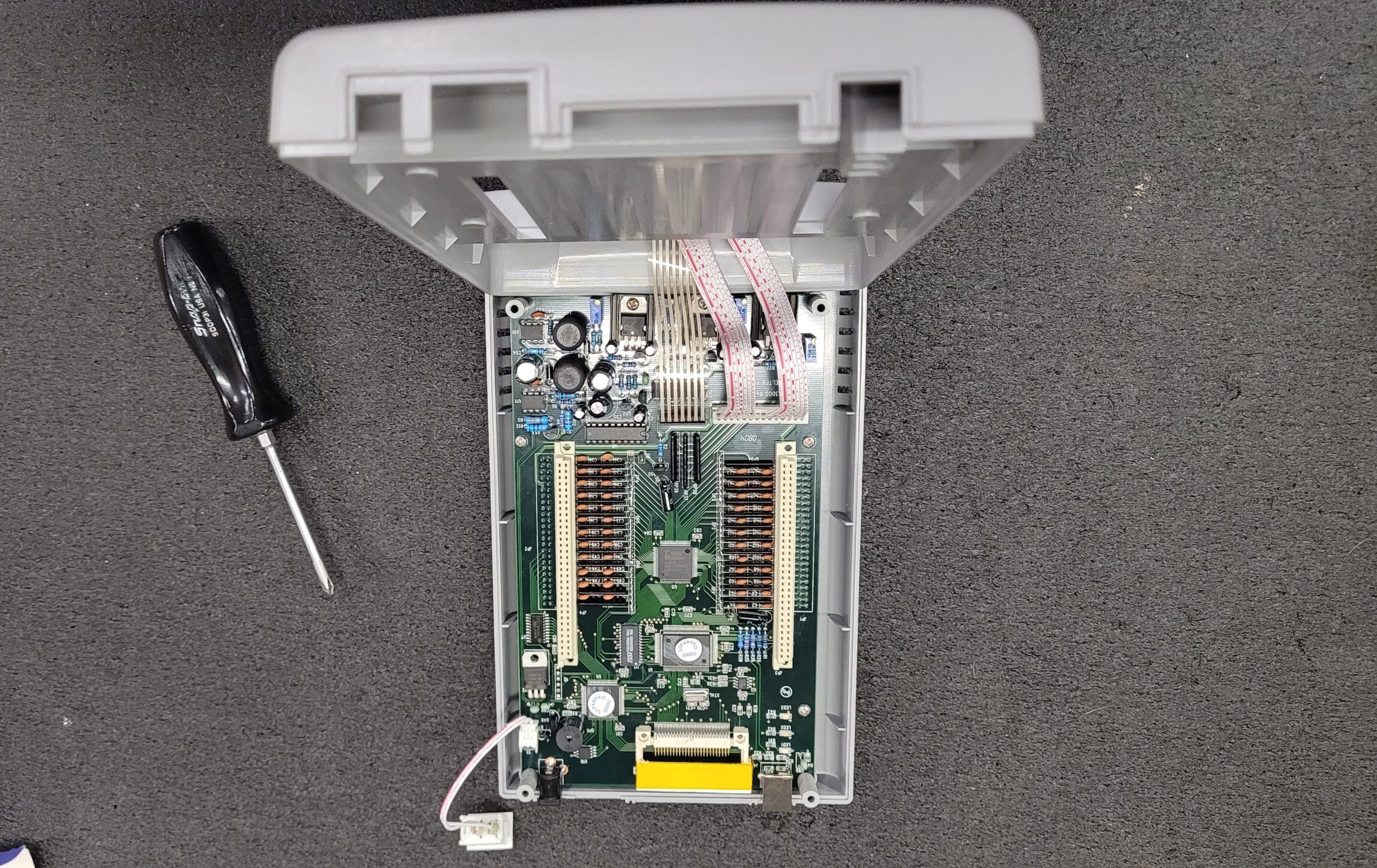
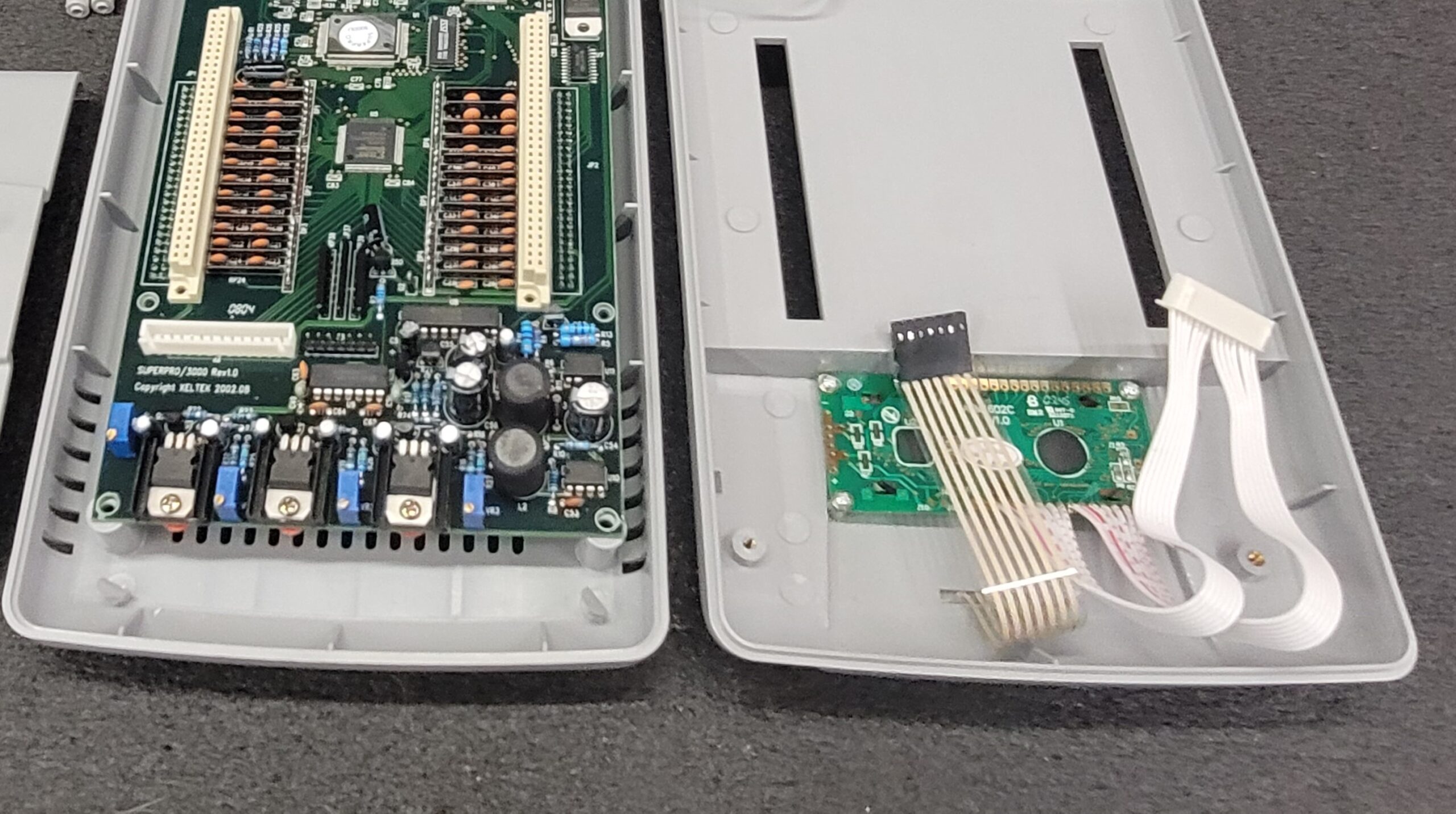
Take note the membrane key pad flex cable is very short Use Caution when disconnecting cable form the header do not pull from flex cable you will damage this cable and replacement membranes are not available. Carefully Pull form the black header connector only! You Will Now have Un Obstructed Access to VR1, Vr2, VR3, & VR4
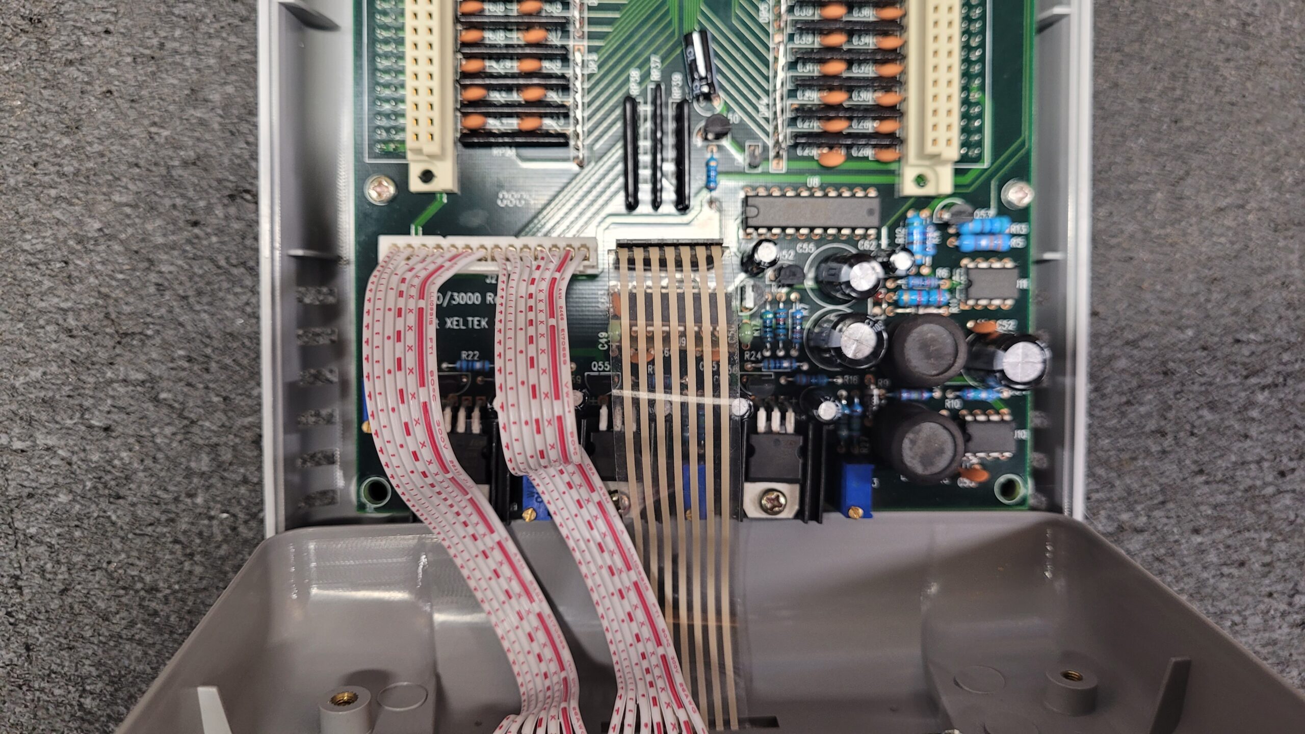
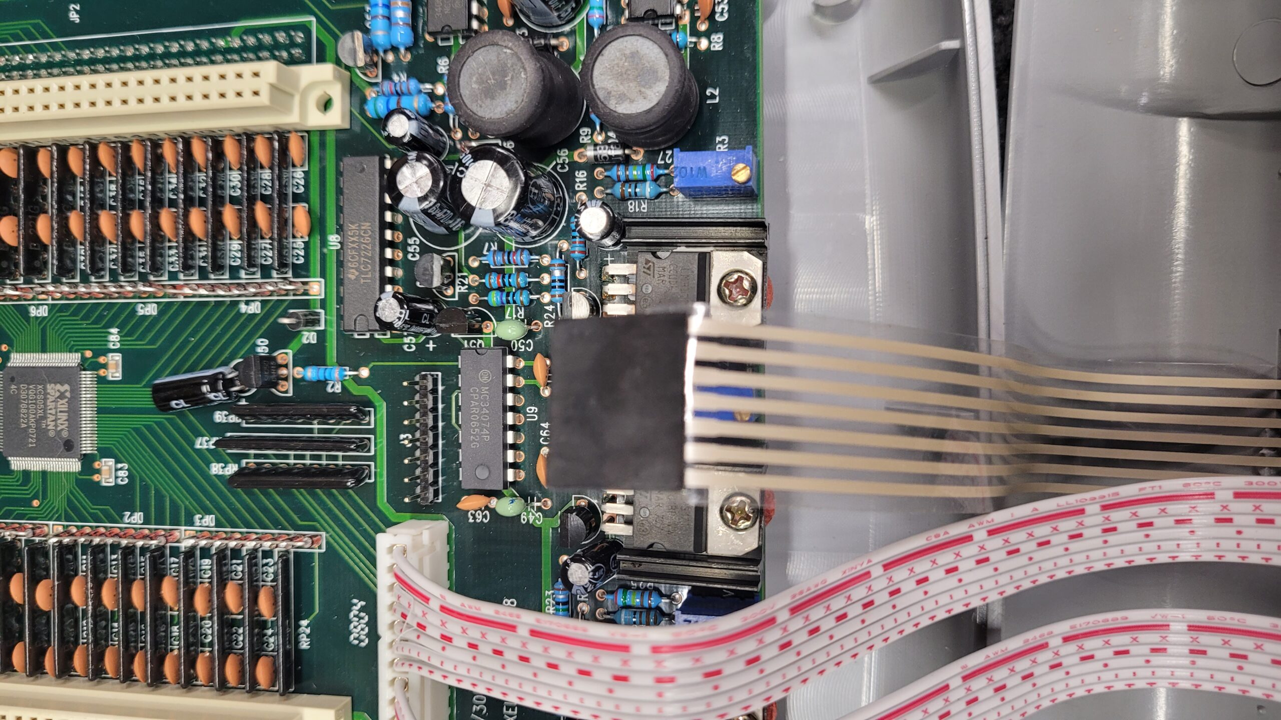
Photo below showing the cover completely removed.
3) Reinstall the socket adapter onto the main board (White Connectors).
(Photo Missing Opps)
4) Plug in power and USB to computer and turn on the 3000U. Allow programmer to warm up for 30min or so.
Location of the 3 LM317T Linear Voltage Regulators 1.2-37V Adj at Q54, Q55, & Q56.

5) Adjust VR4 for best contrast on the LCD display.

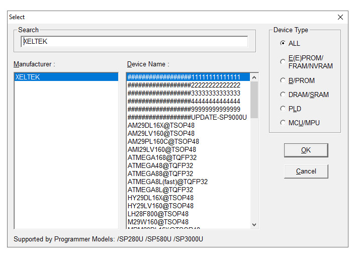
6) Launch the SUPERPRO for Windows software. Click on the ‘Device’ Button. Type ‘XELTEK’ without the quotes into the search box. Select the device called ‘##################11111111111111’ and press the ‘OK’ button.
Select ‘Calibrate’ from the list of operations.
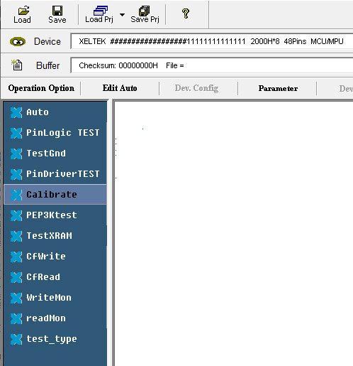
Selecting Calibrate the programmer will run. This will apply 12.0V to Pin 1 of the test socket, 9.0V to Pin 48, and 5V to Pin 25 for several seconds. All voltages are referenced to Pin 2 which is Ground. Go slow adjust one VR pot at a time. Again, It is best to use a quality 5.5 or 6.5 Digit Multi Meter for the adjustments you want the 12V, 9V and 5V voltages as accurate as possible.
7) Adjust VR1. Set the voltage at pin 1 on the test socket to be exactly 12V.

8) Adjust VR2, Set the voltage at pin 48 on the test socket to be exactly 9V.

9) Adjust VR3, Set the voltage at pin 25 on the test socket to be exactly 5V
 .
.
10) Click on Calibration again and verify 12V, 9V and 5V voltages if present then calibration of the Xeltek SuperPro 3000U is complete Reassemble (dont forget the standoffs) you are done. Go burn some chips.
Otherwise, If the voltages cannot be brought into spec (too low) or if the unit will not program high voltage devices (such as 2716’s or 8748’s) then the problem is likely with the MC34063AP1G 1.5 to 40V Inverting regulator ICs Located at U10 and U11. Replace these ICs and all should be working again. Current Mouser Replacements TI MC34063AP.

Additionally when replacing the MC3406AP It is recommend to socket the replacements as they seem to be a high-failure item. Turning the unit off when not in use should make it last longer as these ICs run whenever it is on.
Xeltek Superpro 3000U Electrolytic Capacitor List
10uf 50V X 3 (C69, C68, C67)
1uf 50V X 2 (C65, C57)
470uf 35V X 1 (C56)
470uf 16V X 1 (C55)
470uf 25V X 1 (C54)
22uf 50V x 5 (C61, C62, C58, C59, C60)
Mouser Project List (Verify Whats Installed on Your Programmer)
Xeltek Suprpro 3000U
Right to Repair Score: Undetermined
Last Updated on June 9, 2026 by Steven Rhine
[…] Xeltek SuperPro 3000U Programmer Calibration Procedure […]