Miller 250DX Pulser Sequencer Build
![]()
Supporting a company’s like Miller Electric is undoubtedly commendable and by doing so it brings innovation. However, when a company resort to price gouging and charging customers exorbitantly for accessories and upgrades, it becomes imperative to address this issue. Introducing my Do It Yourself Pulser and Sequencer solutions, designed to empower you to take matters into your own hands. With these innovative alternatives, so you can bid farewell to millers inflated prices and reclaim control over your Tig Welder. The firmware is already in your welder!
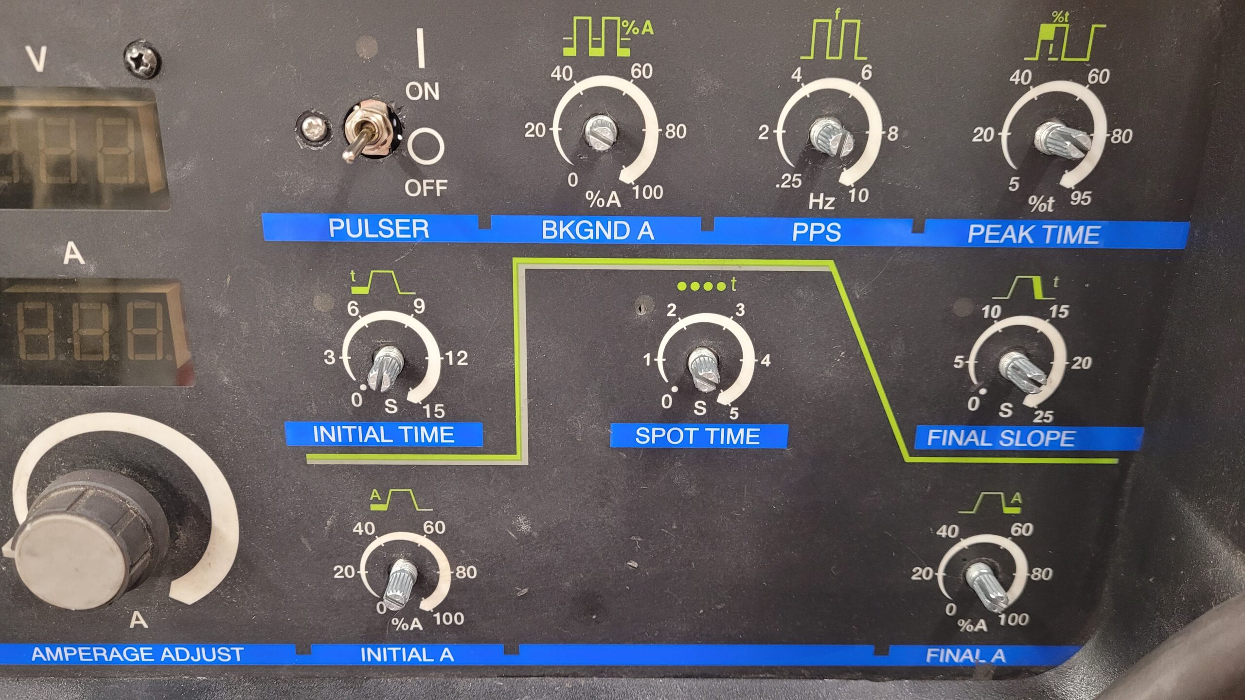
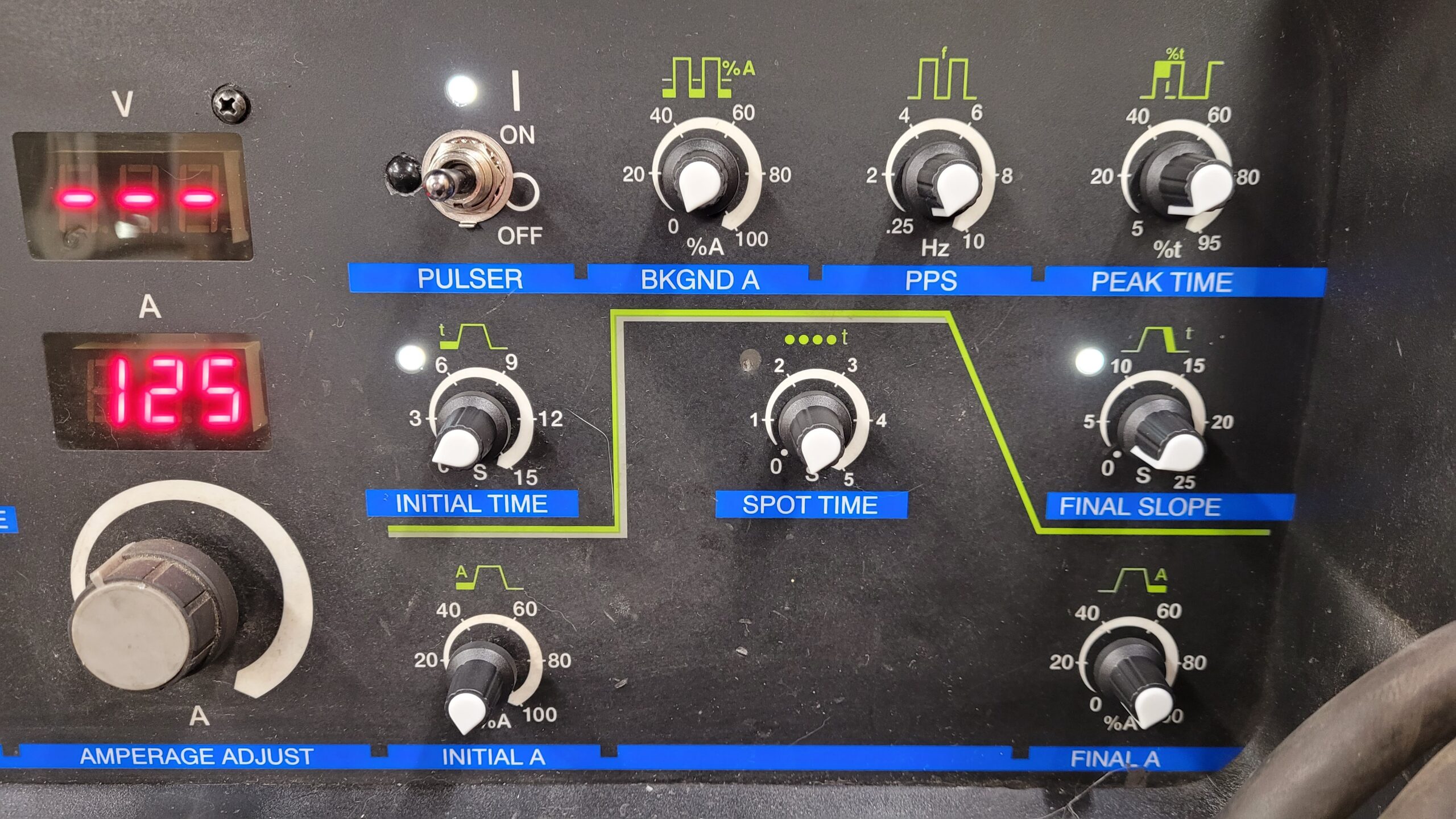
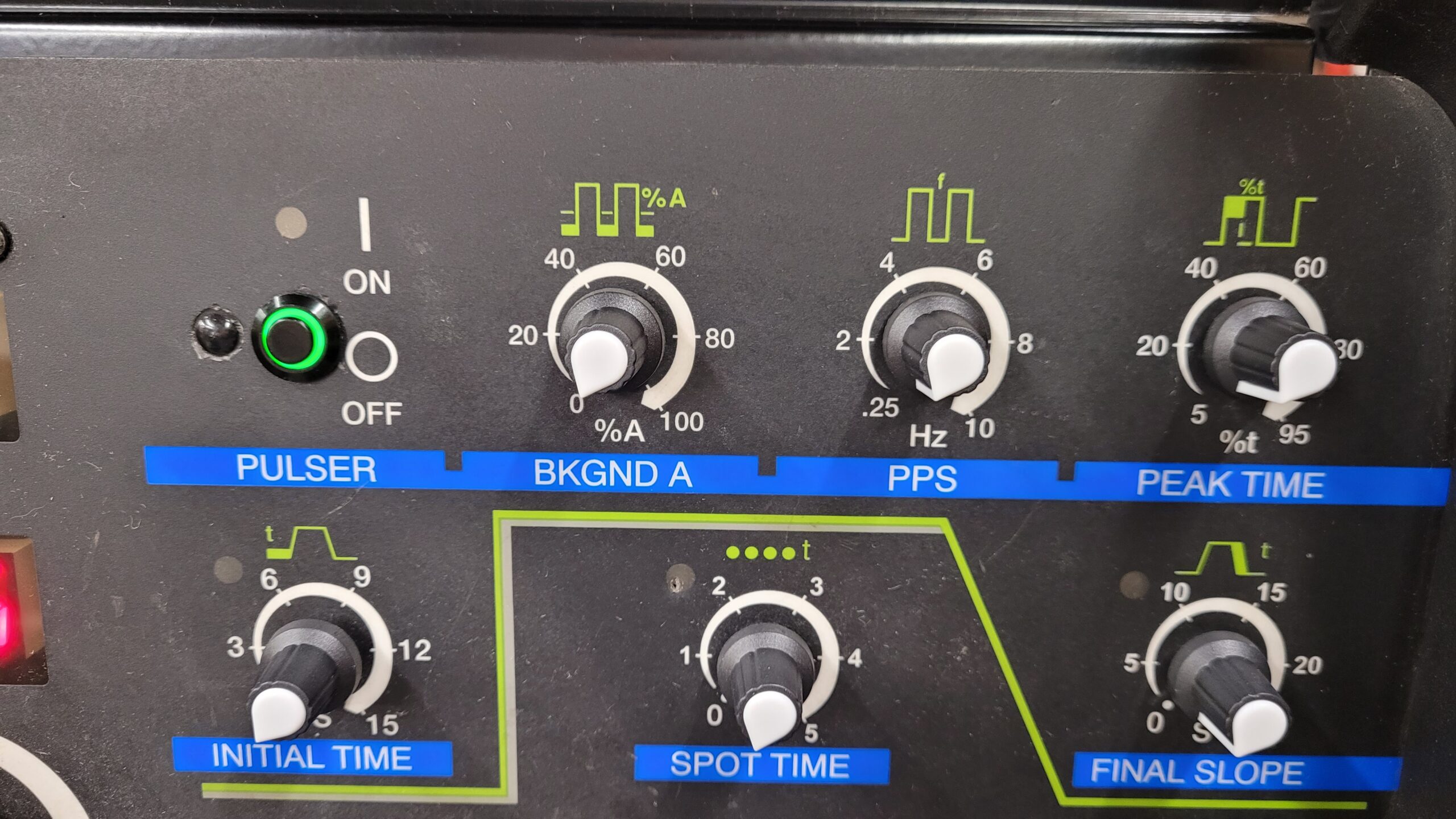
Miller Pulser Option (300548) March 2024 $444.99 Ouch!
Miller Sequencer Option (300547) March 2024 $709.99 Bigger Ouch!
DIY Option #1: Get it Done Fast and Efficiently But Ugly – Dead Bug Style!
If you’re skilled with a soldering iron and can navigate through a basic schematics, we have an incredibly cost-effective solution for you. It’s time to embrace the “quick and dirty” approach and opt for the Dead Bug method. By utilizing this technique, you’ll be able to swiftly add pulser and sequencer to your your miller 250DX without breaking the bank. With a pinch of resourcefulness and a touch of creativity, you’ll be amazed at what you can achieve. For best results use good quality wire and the shortest wire runs that you.
Parts List..
1 On/Off Switch Momentary Normally Open.
1 LED 3.3V
3 10K Ohm Potentiometers .250 (6.35mm or 7mm) Diameter Bushing (Miller uses Clarostat 388 Series V38810KZ Carbon Pots with a Custom Bushing Length)
3 Knobs
1 10 Pin IDC Connector or IDC Breakout Board
Misc. Wire
DIY About $17.00 – $20.00
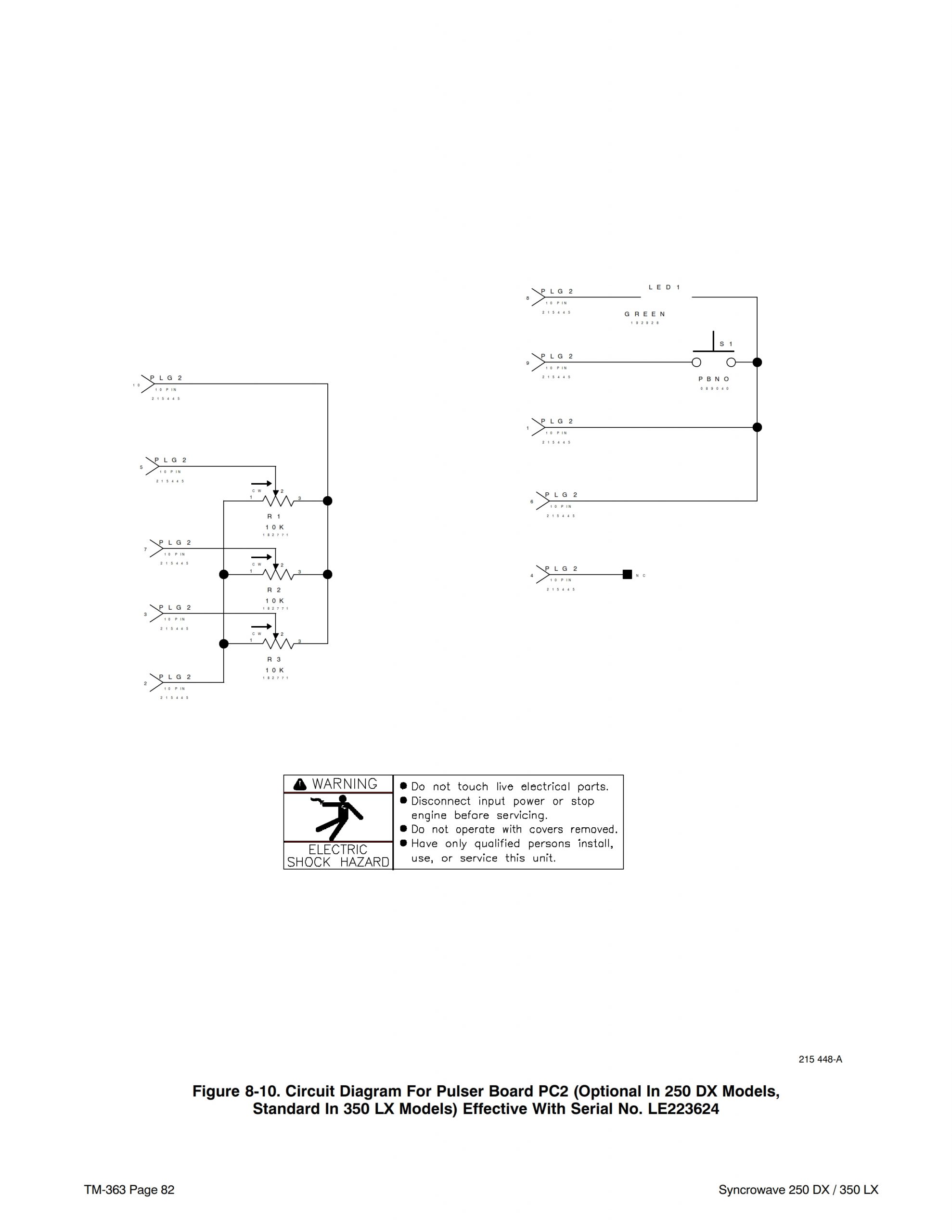
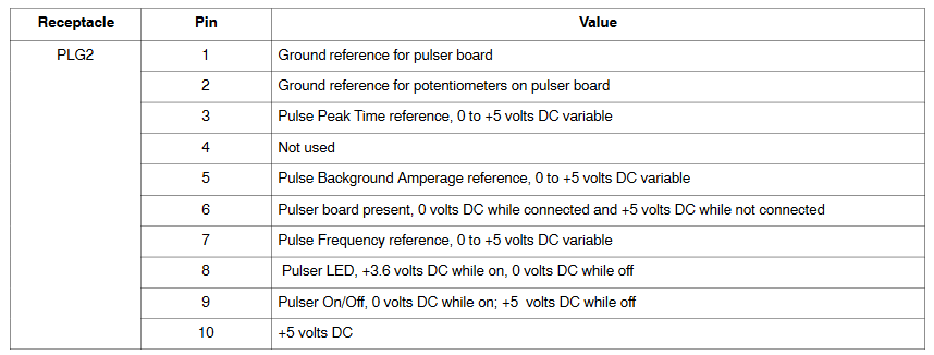
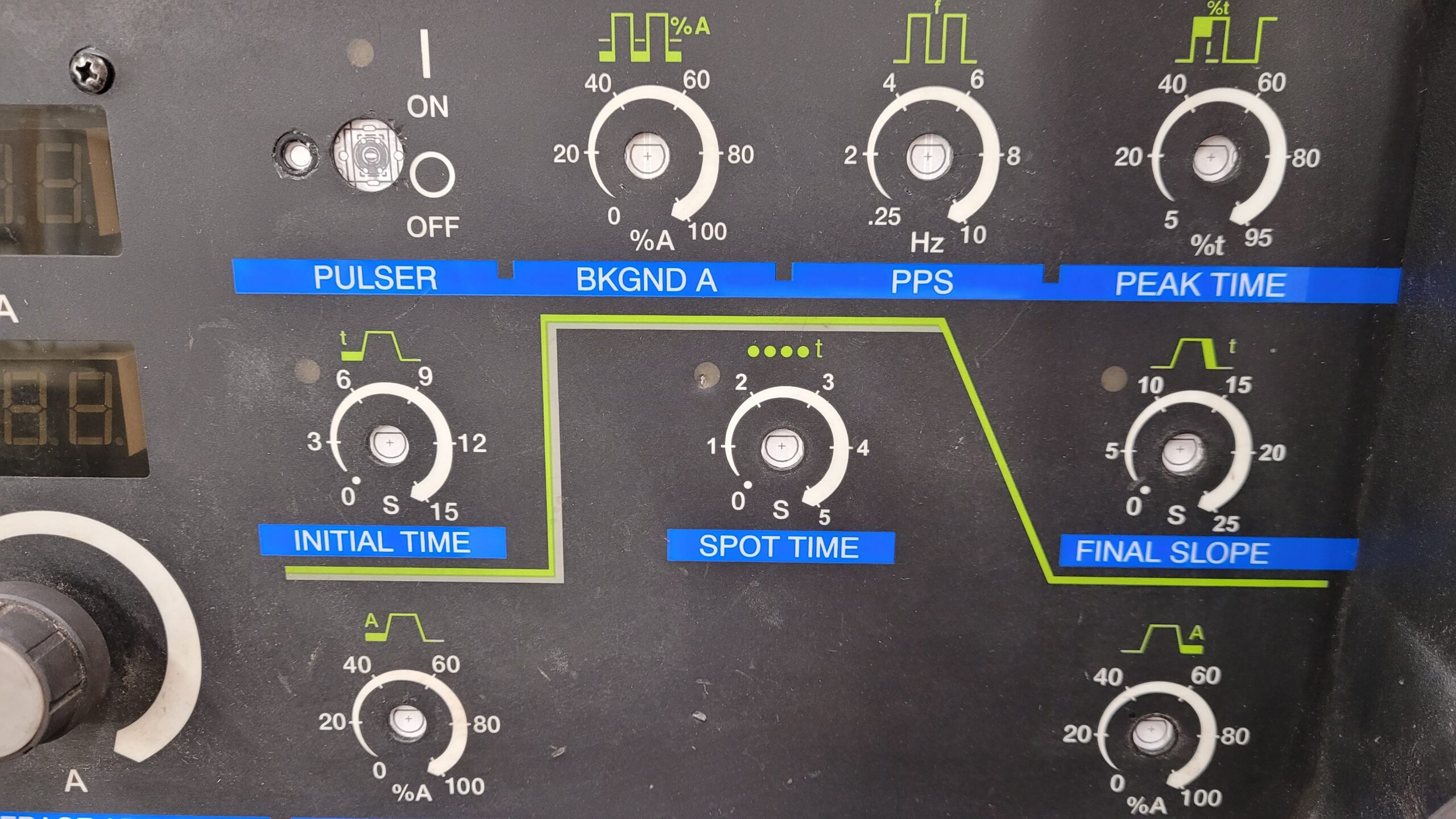
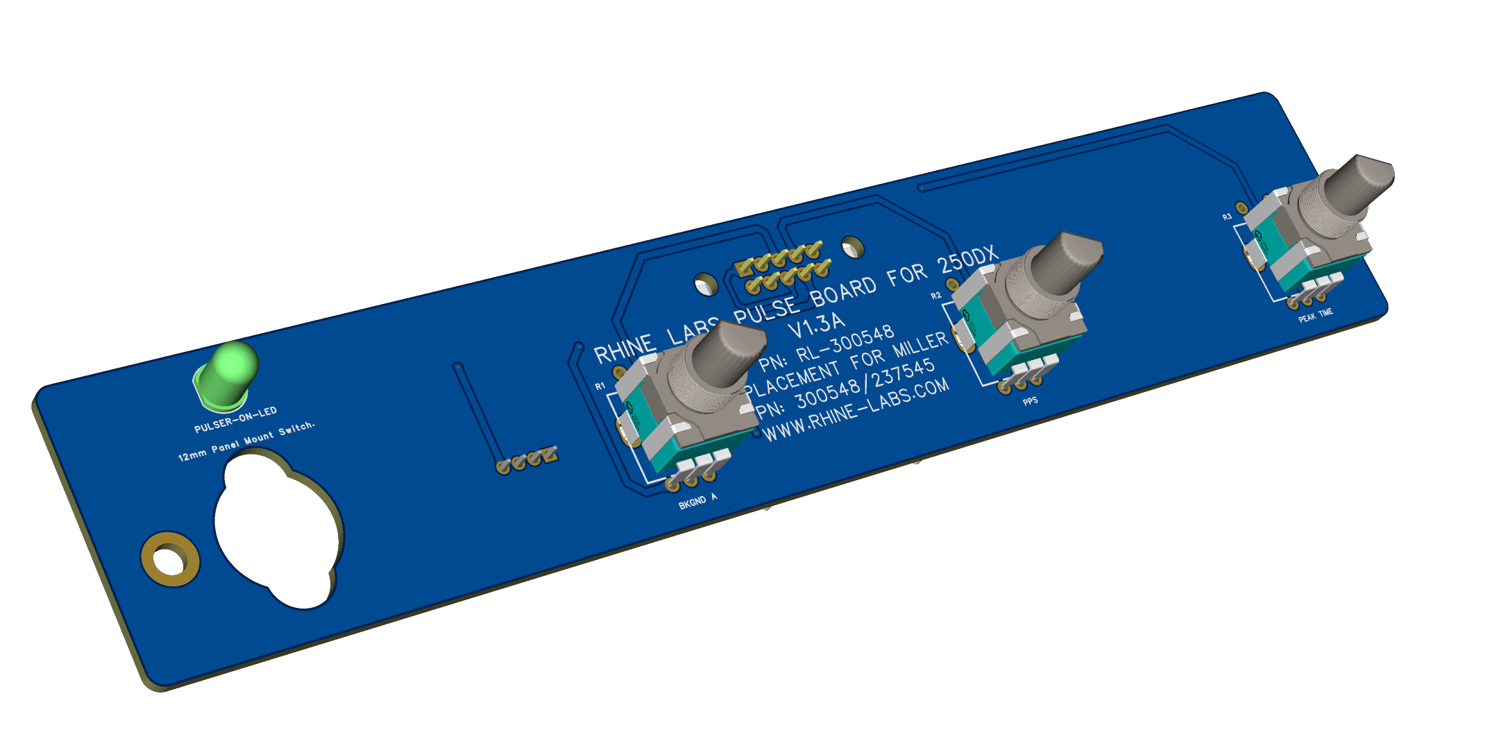
Schematic For Miller 250DX/350LX Pulser Option
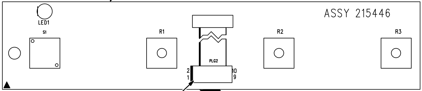
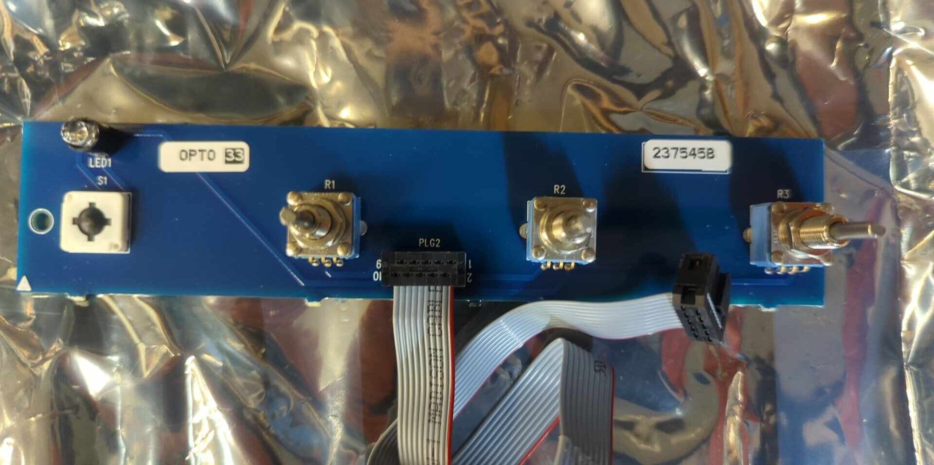
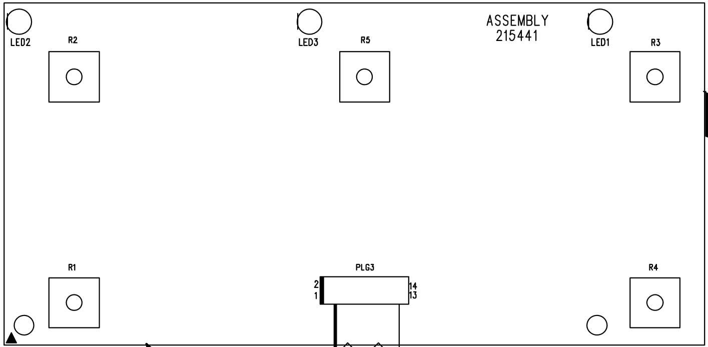
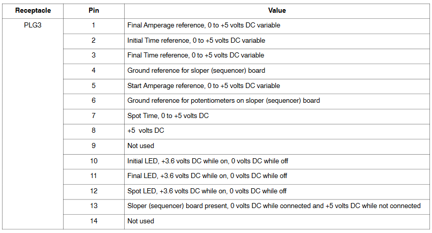
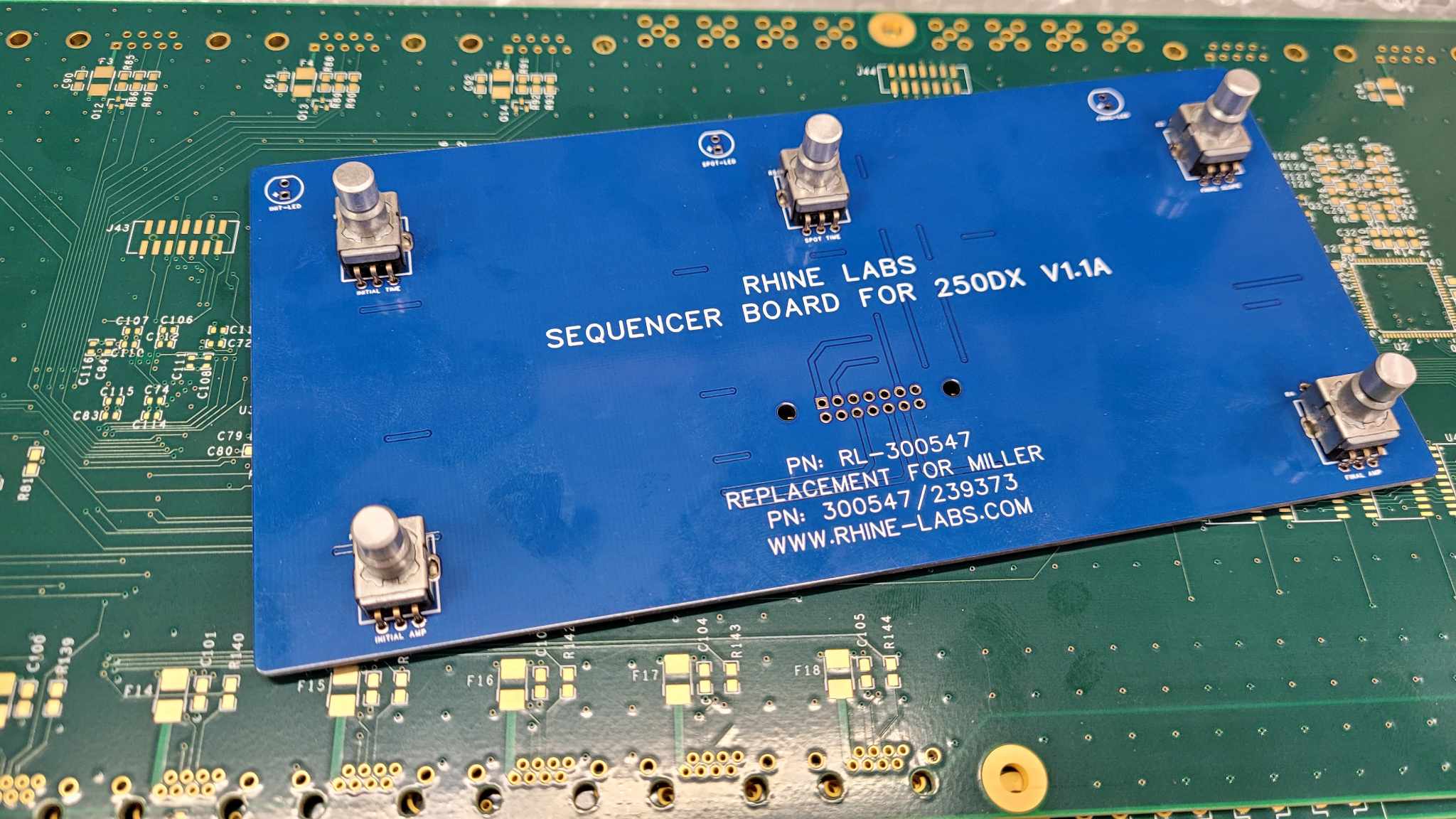
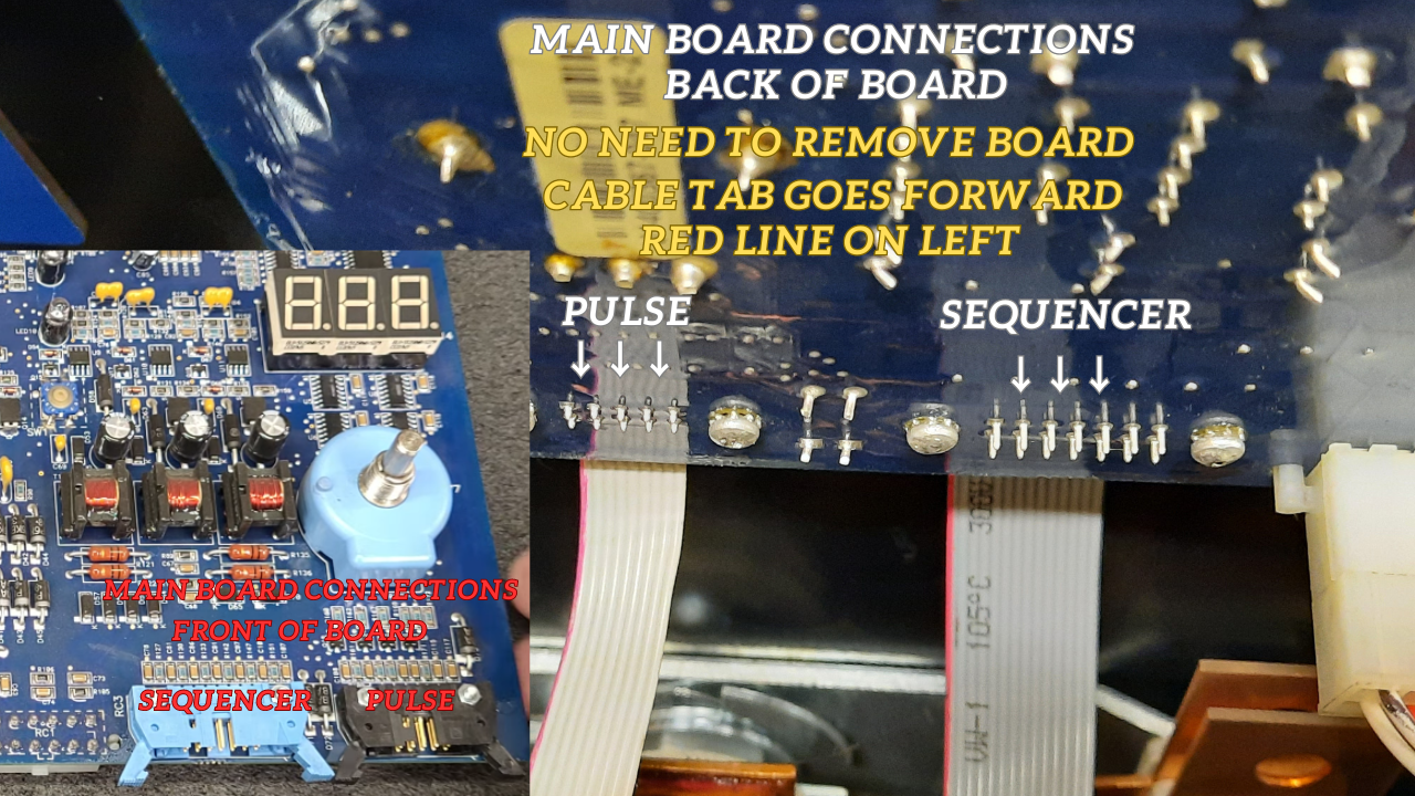
250DX Pulser Panel Layout and IDC Connector Pinout
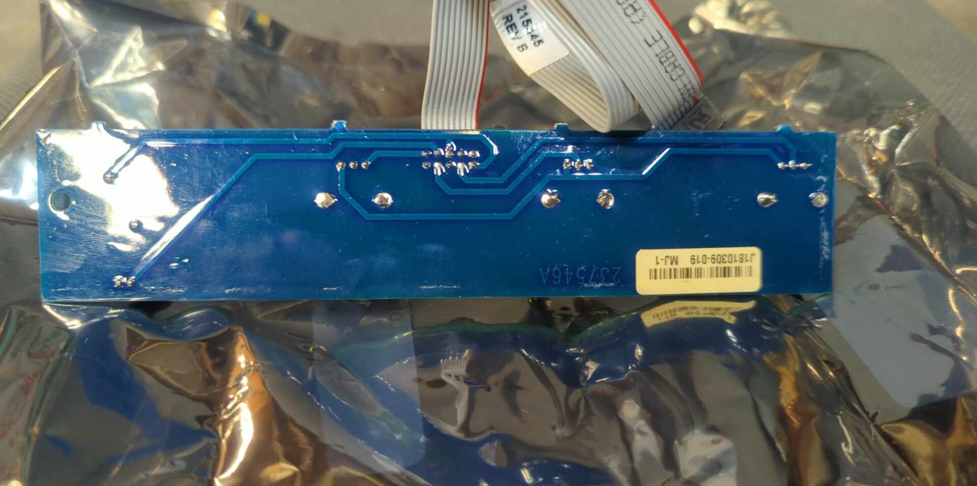
Updated September 08 2023: Thanks to A Facebook Group Member I now Have Photos of the Genuine Miller Pulse Board.
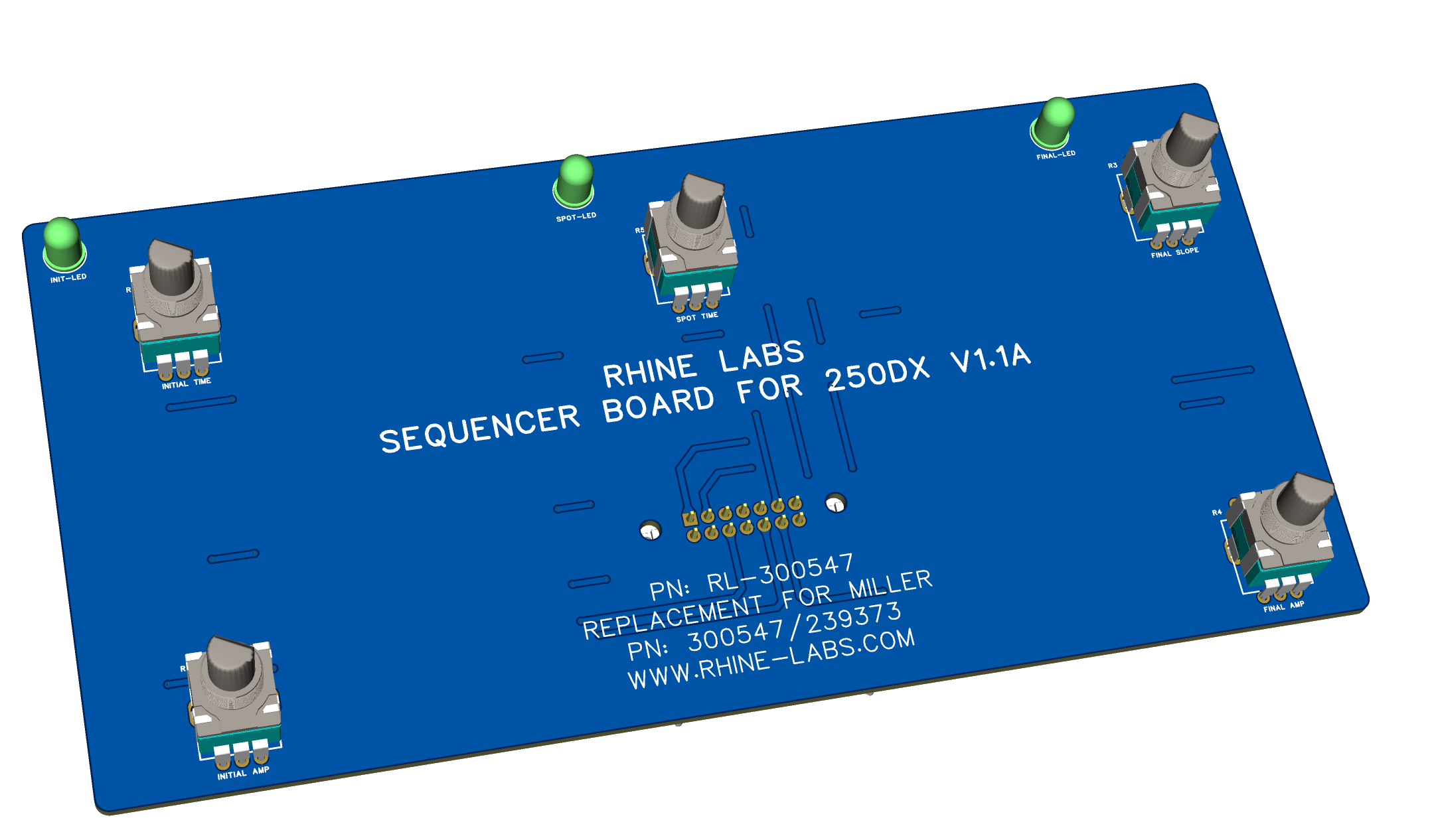
Miller 250DX Sequencer.
Parts List..
5 10K Ohm Potentiometers .250 (6.35mm or 7mm) Diameter Bushing (Miller uses Clarostat 388 Series V38810KZ Carbon Pots with a Custom Bushing Length)
5 Knobs
3 Led’s 3.3V
1 14Pin IDC Connector or IDC Breakout Board
Misc. Wire
Diy Dead Bug About $20.00 – $35.00
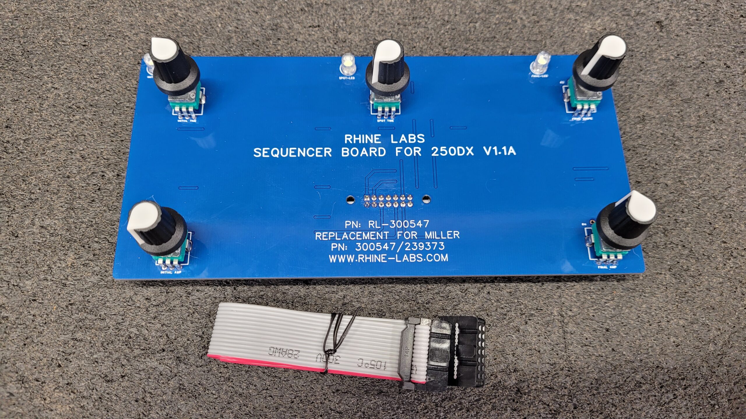
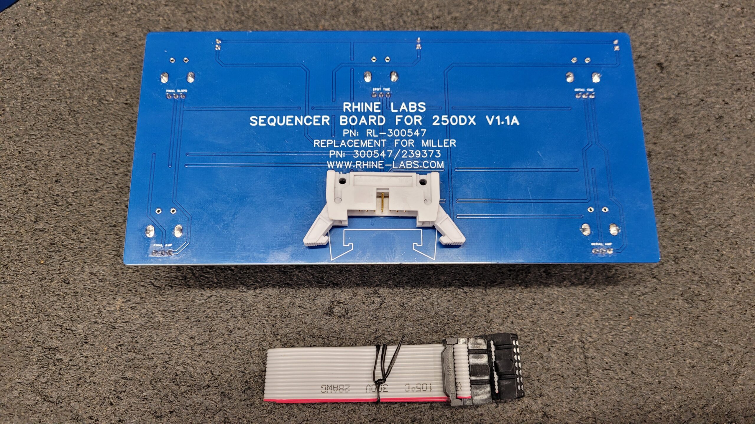
Schematic For Miller 250DX/350LX Sequencer Module
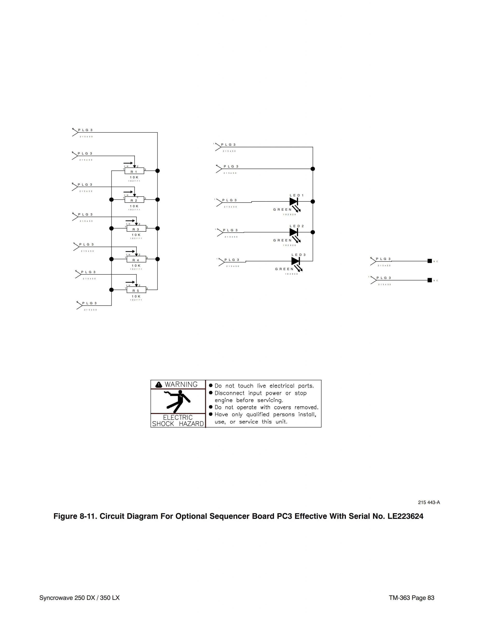
Sequencer Panel Layout and IDC Connector Pinout
Dead Bug Style is not be a complex project you will prob spend more time sourcing pots and matching knobs. I Would recommend you use a name brand Alps, Bourns, Etc. for the Potentiometers they are way less cost then miller is charging for their replacement pots.
Option #2: Get it Done Fast, Efficiently And Clean! Buy One Assembled?
Exciting News! July 2023.
Attention all tech enthusiasts and DIY aficionados! Brace yourselves for a thrilling update. I am delighted to inform you that I am currently in the process of designing a custom circuit boards for this project. I’m considering offering DIY Kits “for a small charge” that will enable individuals like yourself to experience the joy of assembling and building this project firsthand. Furthermore I may aslo offer a fully assembled version. Stay tuned for further updates, as this promises to be a remarkable journey.
I Have decided against making assemble your self kits during beta testing the tech support for this exceeded the time for just assembling the baords. You can still do a DIY Dead bug build if you wish.
This is all because of Miller’s Prices have gone form Insane to Go F-Yourself price gouging!! WTF $445.00 to $710.00 for a PCB With only a few parts and No Logic? Nope Not Having any Of That!
I’m thrilled to share that I’ve recently moved this project up on my list of priorities. In fact, I’ve already dived headfirst into the Circuit Board design for the Pulser and Sequencer! I’m actively exploring various concepts and refining the design to ensure optimal fit, performance and functionality.
07/06/2023
Exciting news! My Sequencer Prototype is nearing its final stages almost ready to have sample boards made
Building upon the unimpressive Miller Board, I’ve gone the extra mile to incorporate some game-changing enhancements. I’ve added teardrop solder pads and vias, ensuring optimal signal integrity and seamless connectivity throughout the PCB. To further enhance durability and reliability, we’ve introduced copper pours on both sides of the board, delivering exceptional conductivity and shielding capabilities.
Taking extra measures to ensure a flawless fit. I currently in the process of 3D printing a model, which will be meticulously examined in the machine to verify it’s a perfect fit. Rest assured, I am leaving no stone unturned to deliver an impeccable and affordable DIY solution.
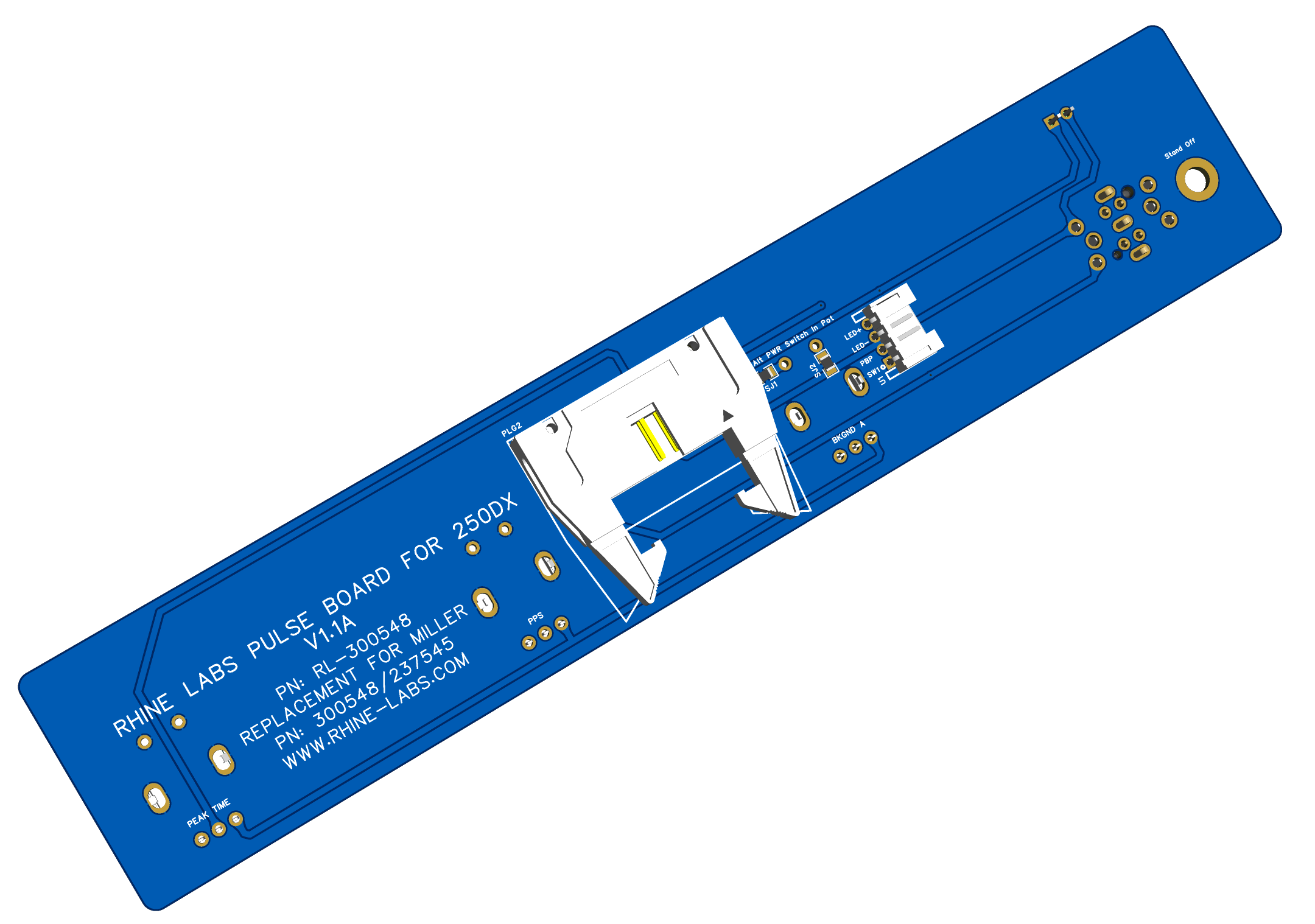
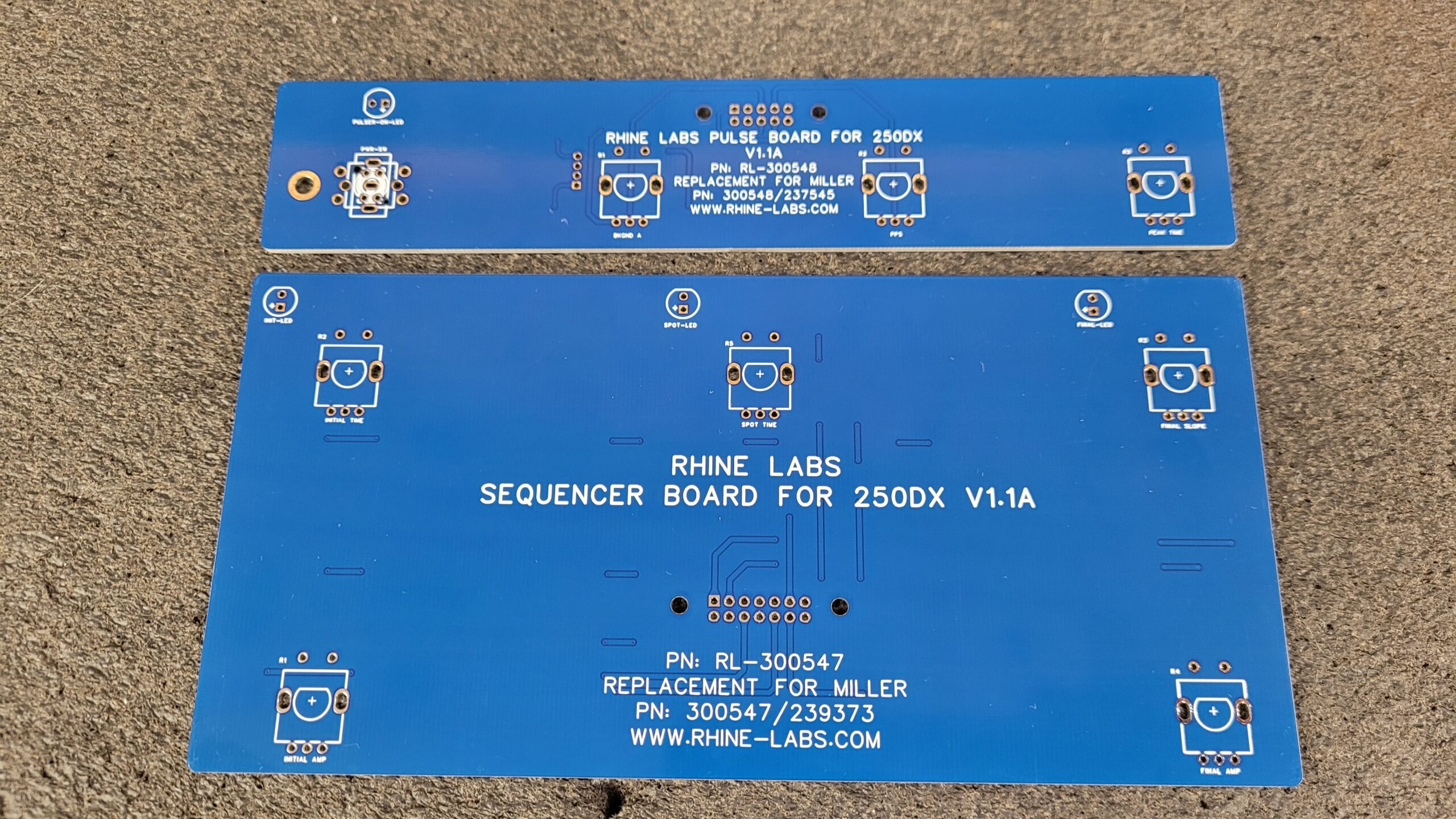
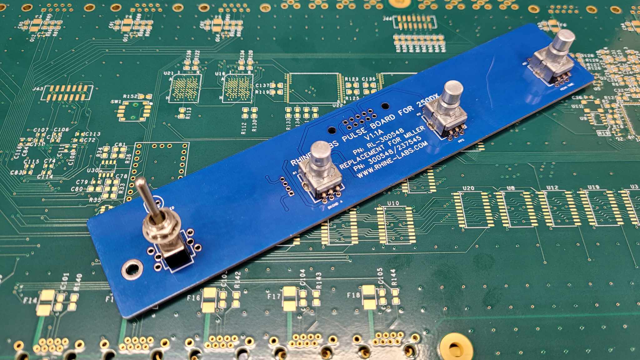
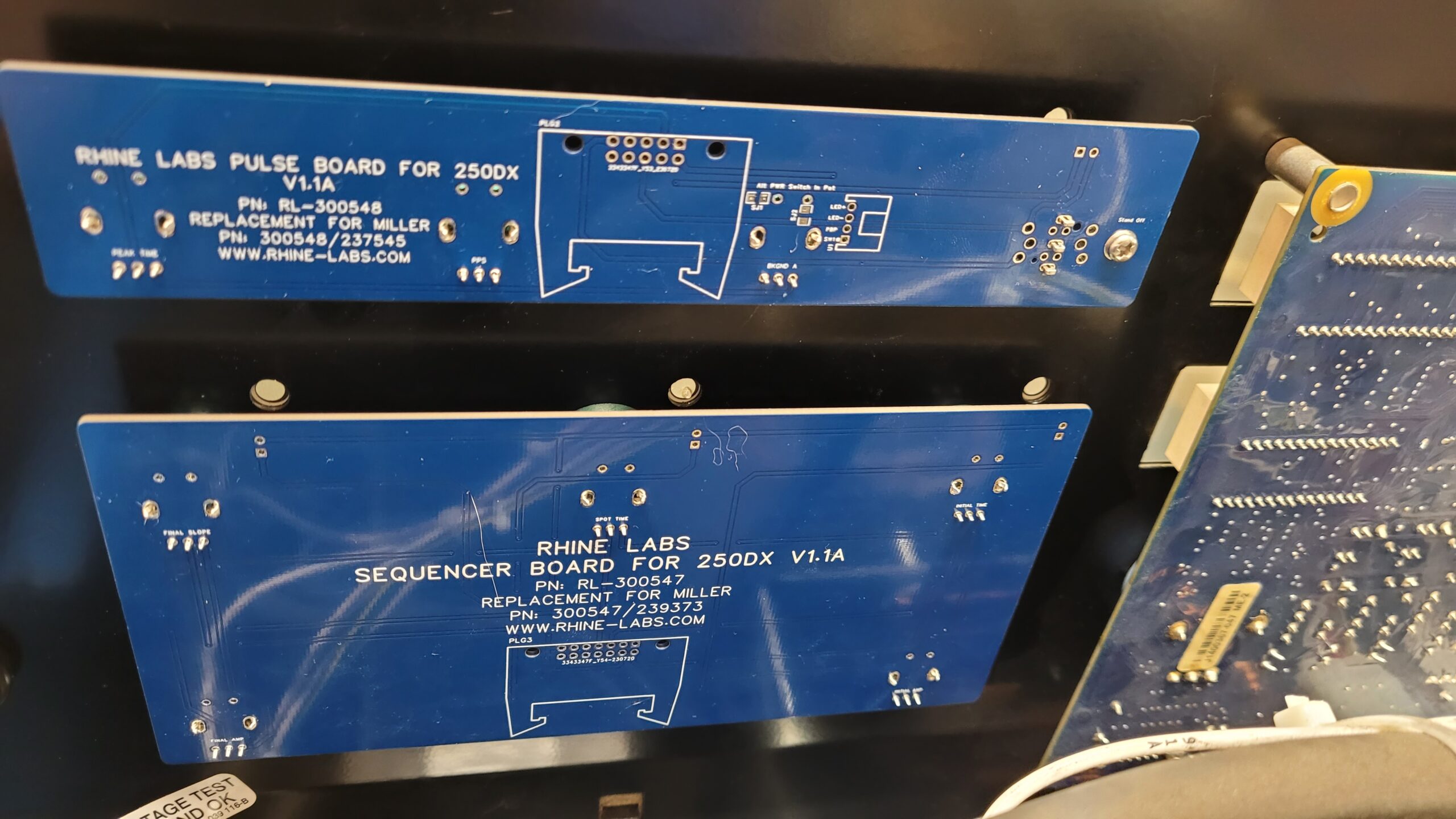
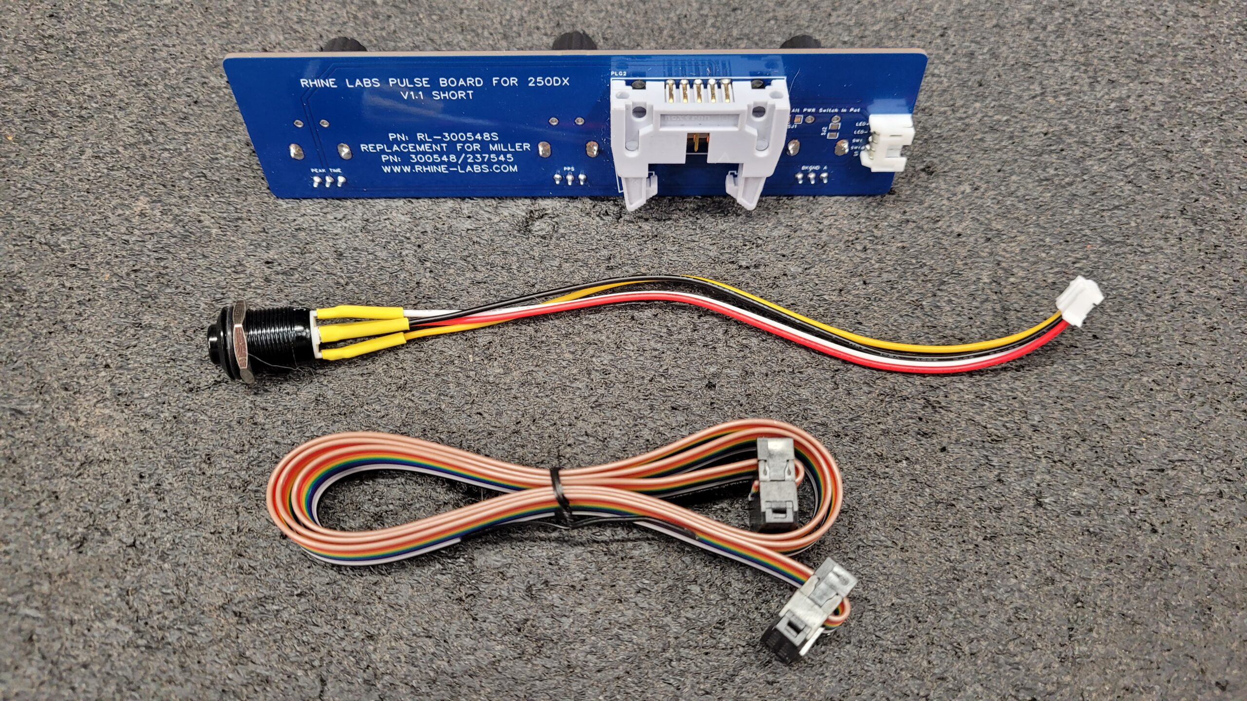
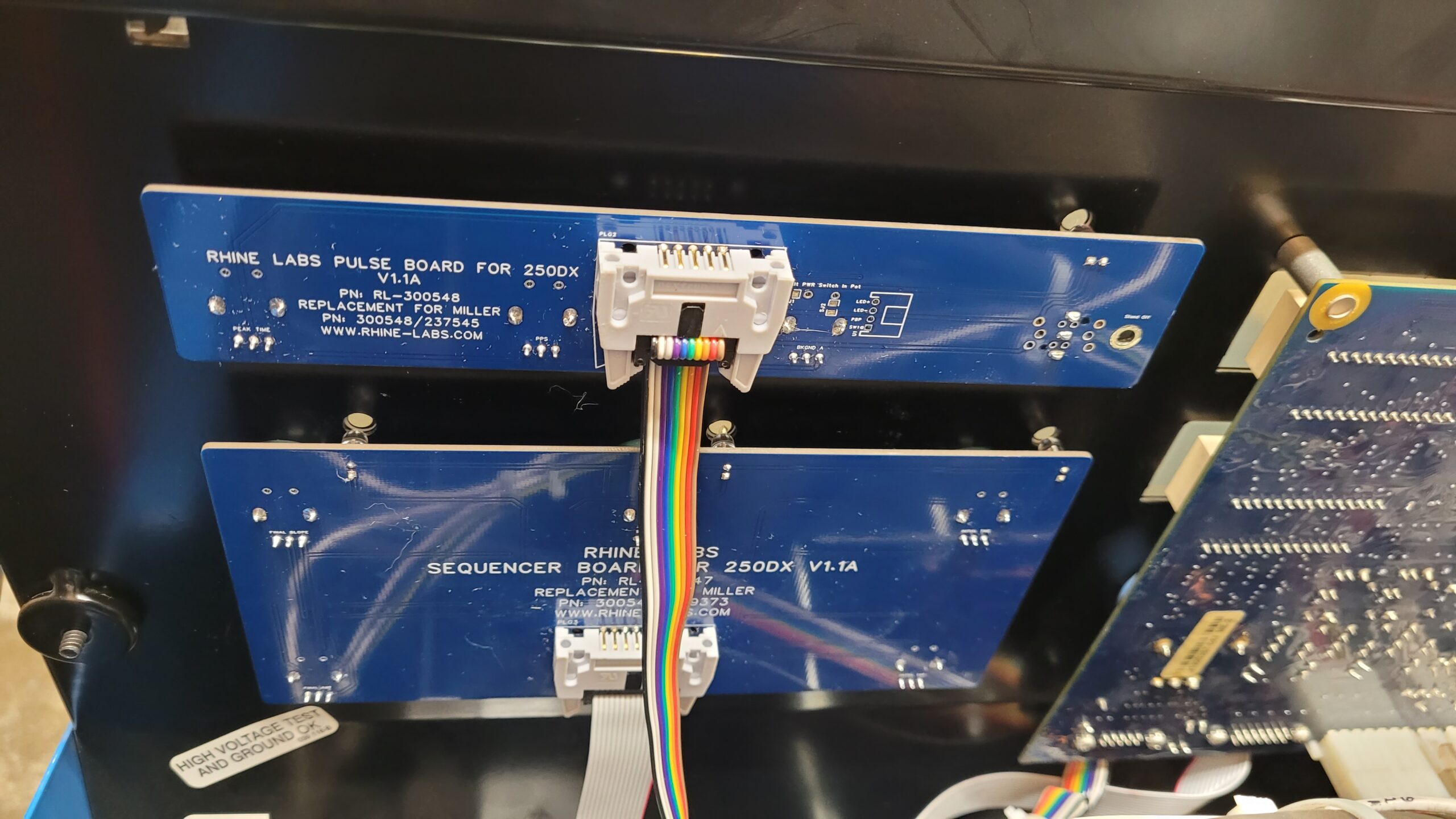
Based on invaluable feedback and insights from the welding community, I’ve made notable enhancements to the Miller Pulser Board. Recognizing the notorious reliability issues of the miller 250dx switches, we’ve taken the initiative to add a much-needed toggle switch. No more struggling with clumsy attempts to engage the pulser with gloves on. I have made this board so you can still use the miller push switch I give you the choice of which to use. I’ve also included a locking IDC connector on the back no more loose cables.

07/10/2023
Introducing the Sequencer Prototype: A Remarkable Step Towards Completion!
My Sequencer Prototype is nearing its final stages also and almost ready to have the sample boards made, and I can’t contain My enthusiasm and just had to post a photo of it.
After conducting an extensive search on the internet, including the welding forums and archives, I must admit that my efforts yielded only one photo of an Original Miller Sequencer Board. Regrettably, I was unable to locate any images of the Miller Pulse Board. It seems that such images do not exist, and the only images found were of Miller’s antistatic packaging concealing the PCB. This lack of transparency raises questions about why they might not want potential customers to have a clear view of what they are purchasing.
Nonetheless, I will remain vigilant and continue to monitor the web for any updates or additional sources that may eventually provide the desired image of the Miller Pulse Board. If anyone has a photo of the original boards send me a message.
There’s no way Miller should be charging $400-$700 for this simple board! Each day, I’m making significant progress in it’s development, and I’m getting closer to completing it. Stay tuned for the final unveiling, as I’m really excited to share the results with you all. Once the PCBs arrive, I’ll make a YouTube video of the unboxing, so you can see them firsthand.
07/13 I Only have a one thing on my “to find list” and that is the part # for Miller Part #089040 which is the power switch. I would like the PCB to have the footprint to run the same Switch. As soon as I find the switch I will add the footprint to the PCB and order the prototypes. Even the Measurements and Photo of the OEM switch would help. So if any of you know or have access to the pulse PCB let me know.
07/14/2023
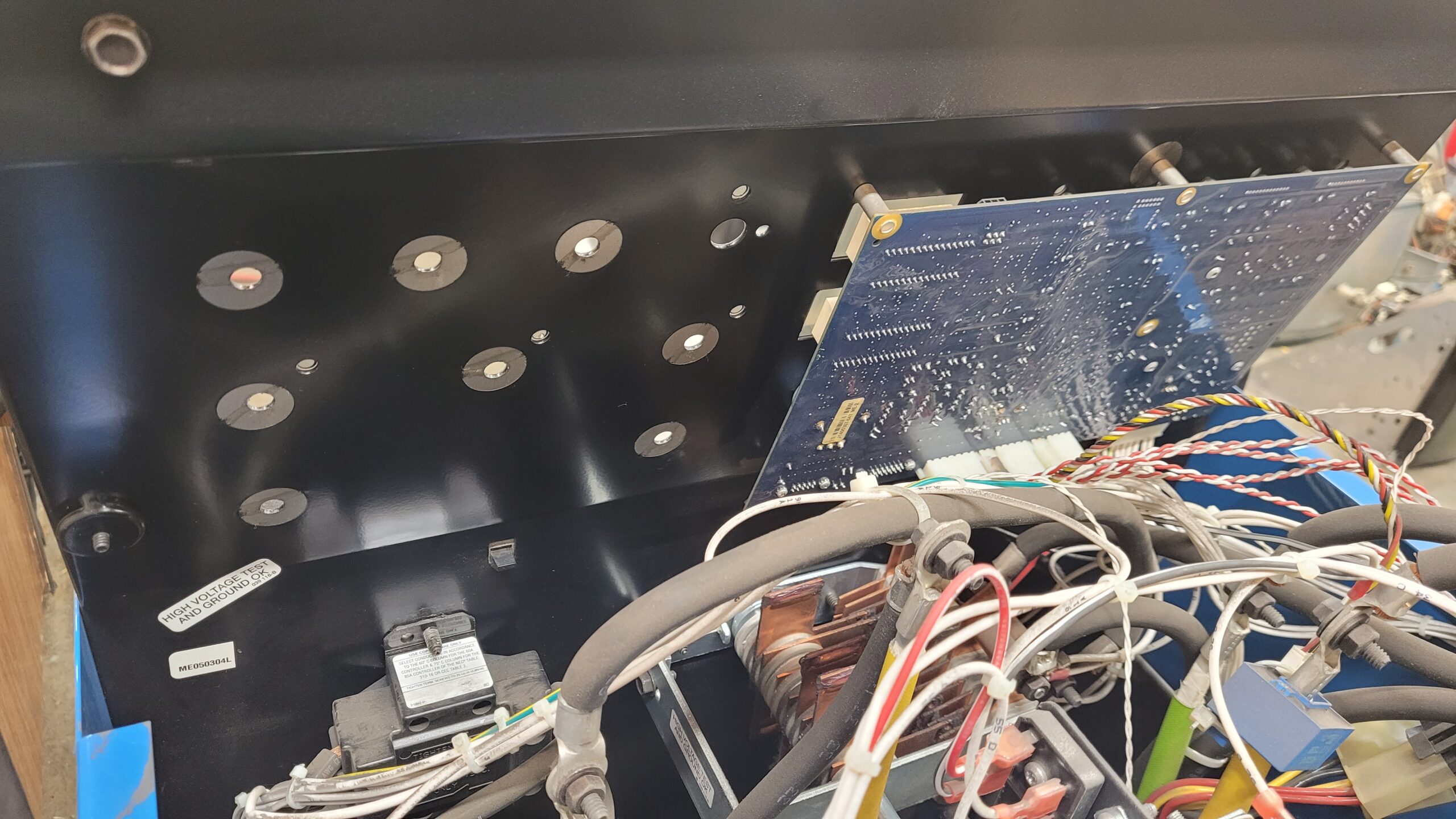
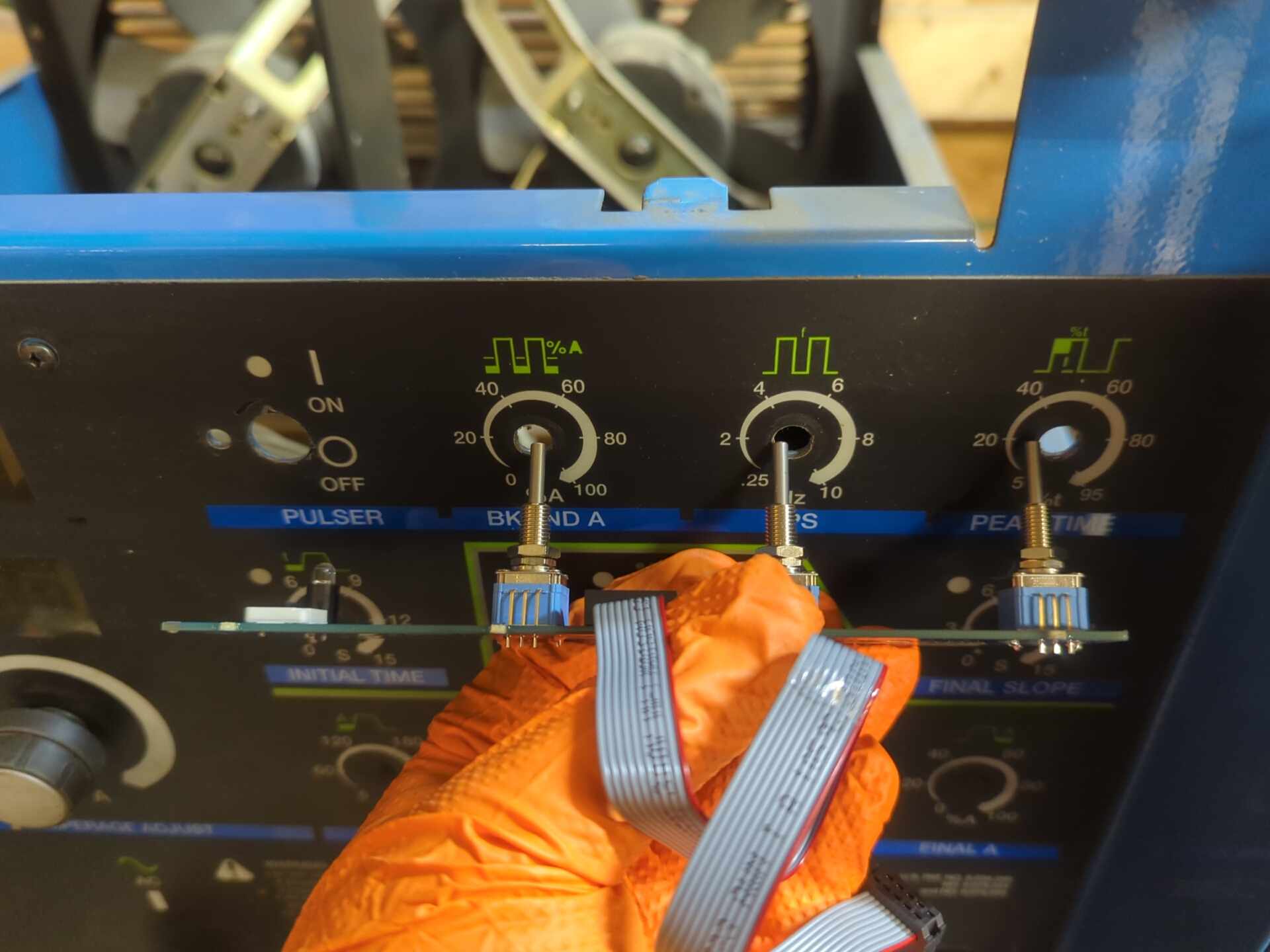
Machine Disassembly.
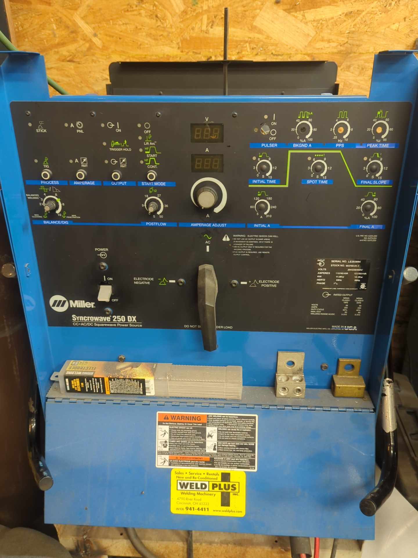
Upon inspecting the interior of the Miller 250dx Tig Welder, it becomes evident that there is an abundance of space available for mounting the Pulse and Sequencer PCBs. The generous layout and design of the welder’s interior provide ample room to accommodate the printed circuit boards comfortably. This well-thought-out arrangement not only ensures that the PCBs fit efficiently but also contributes to the overall ease of maintenance and servicing.
With such ample space, it is apparent that Miller has carefully considered the practicality and functionality of their design, ensuring that the PCBs can be installed and accessed with convenience. This thoughtful approach is likely to enhance the welder’s reliability and serviceability, making it an attractive choice for users seeking a robust tig welder.
Modeling & Fitting Potentiometers, Switch and LED Layout.
Despite my best efforts, Fusion 360 did not cooperate as expected, and unfortunately, with my lack 3d modeling skills I couldn’t figure it out. So creating 3D printed scale models for fitting and alignment did not happen. Instead, I decided to take a more traditional old school approach by utilizing paper and tape to achieve the desired fit.
Although I encountered a skills’ setback with the digital modeling method, resorting to paper and tape allowed me to still achieve accurate representations of the component placements. The hands-on approach provided a practical and tangible way to assess fitting and alignment for the project. While 3D printing may offer big advantages in certain situations, sometimes going back to traditional methods can prove effective and reliable for prototyping and testing purposes.
One day, I will find the time and cultivate the patience required to sit down and learn the 3D modeling software properly. While the learning process may be challenging and demand dedication, I am eager to embrace the journey and build my proficiency step by step.
I encountered challenges in locating the specific power switch used by Miller. Consequently, I decided to opt for the ALPS SPEF110200 as it closely matches the height of the Potentiometers, with a slight mil difference. Additionally, I provided the option to use a miniature momentary toggle switch along with a JST Connector as a prototype alternative.
Ordering The Circuit Boards
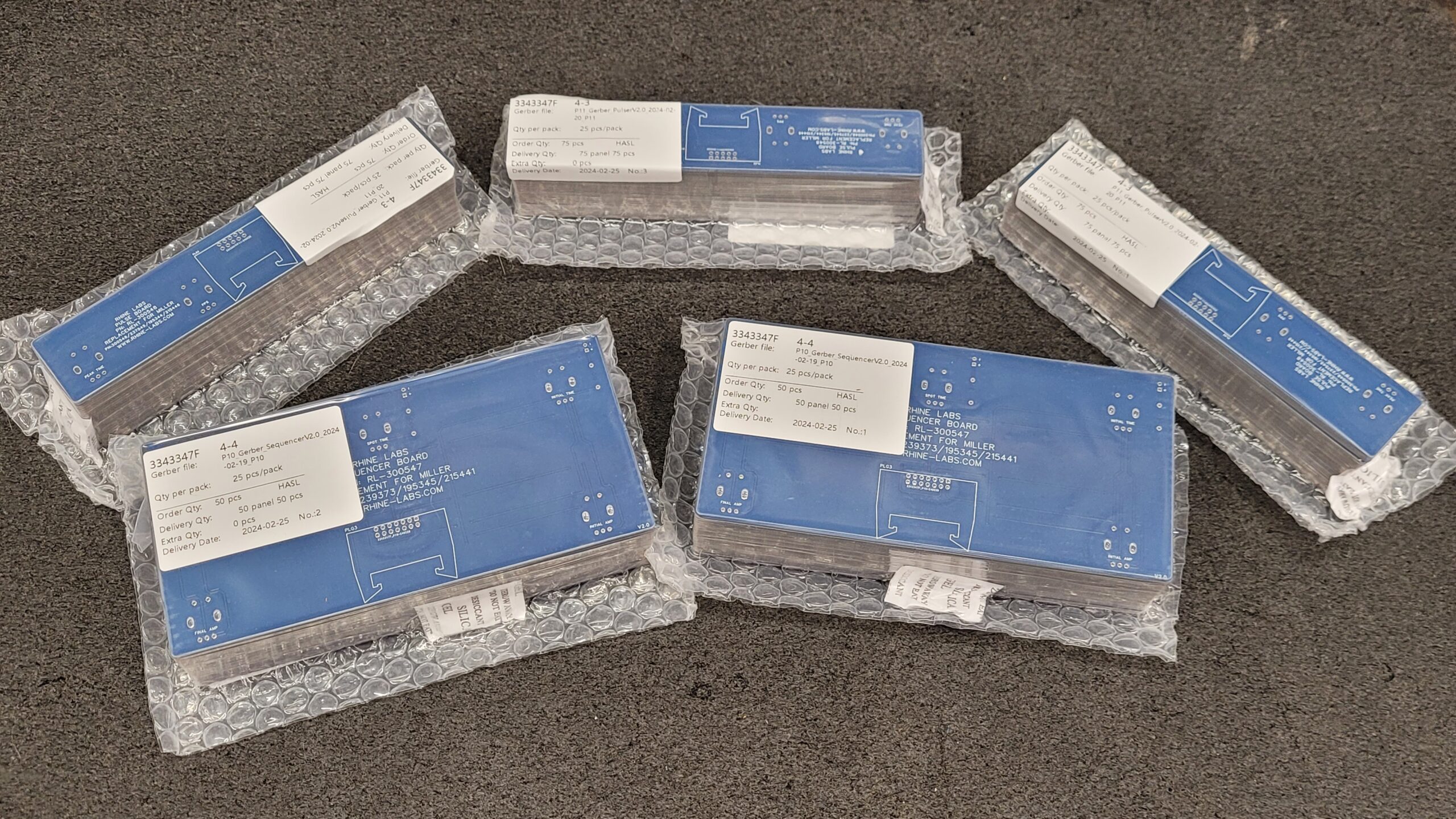
To expedite the project, I went ahead and placed an order for some Circuit Boards on July 20, 2023, starting with 20 PCB’s that is 10 of each. This choice appeared to be the most cost-effective and efficient solution for getting the boards quickly. Please be aware that the FJB will not be included on the boards.
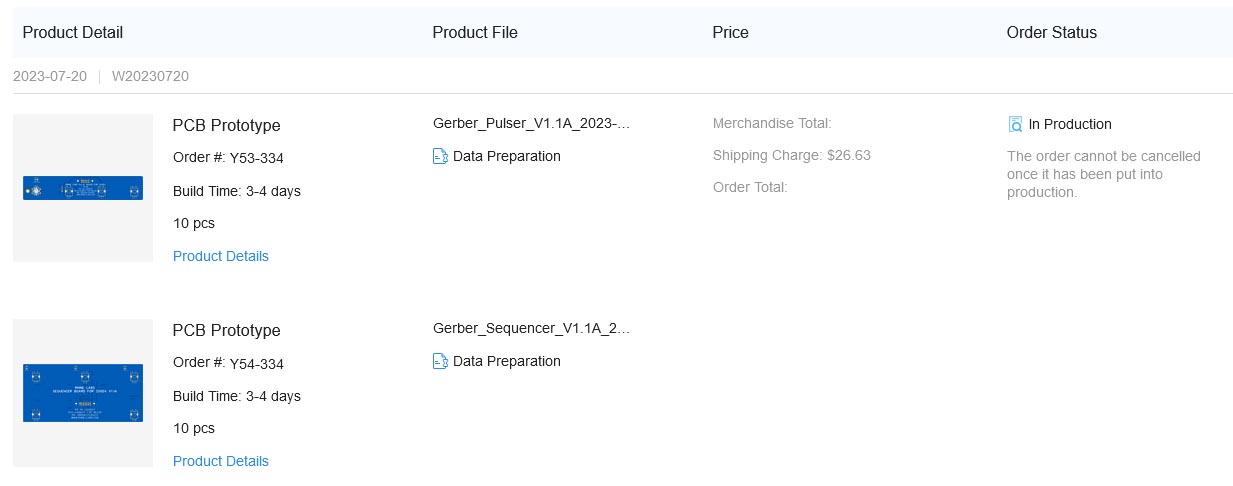
On Friday Morning July 21, 2023, I eagerly checked the progress of the PCB production, and true to form, JLCPCB’s service proved lightning fast once again. I am pleased to report that the PCBs are nearing completion and will soon be ready for delivery. Once more, their efficiency and quick turnaround time have left me thoroughly impressed.
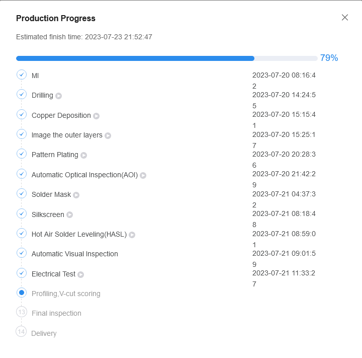
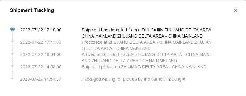
The boards were completed at the PCB fab on July 21st and are now ready for carrier pickup, which took approximately 2 business days. However, since it is currently the weekend, I’m uncertain if DHL operates pickups on weekends or not. We may need to wait until the next business day to find out if the boards will be picked up for delivery.
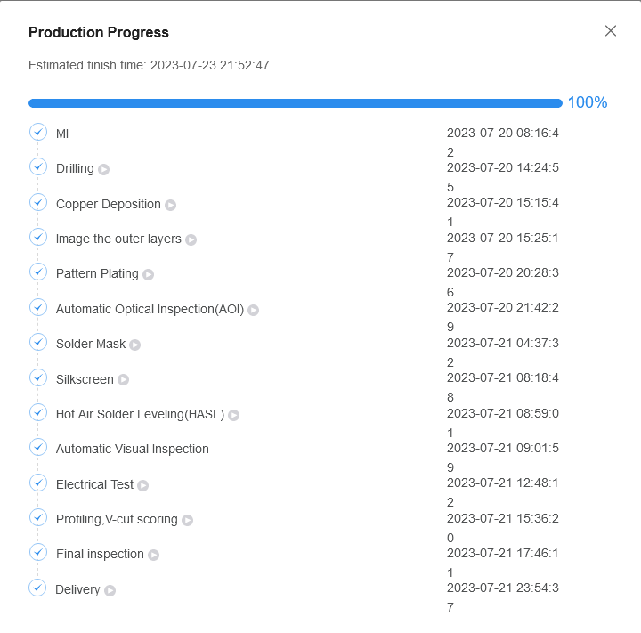
Great news! DHL picked up the PCBs on July 22nd from the fab, and they should be at my doorstep within the next 2-4 business days. This means I can promptly proceed with the project and assemble one as soon as the parts arrive they are on the slow boat trip. This project is finally nearing completion, and I couldn’t be more excited!
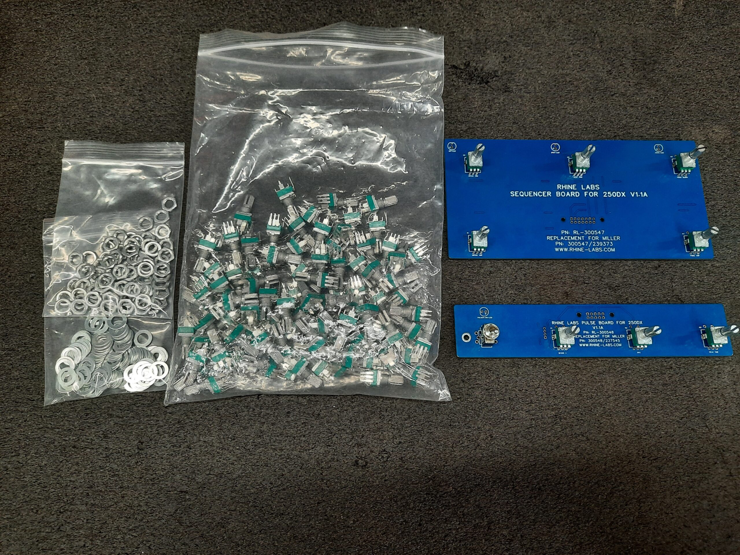
For this project, we have chosen to incorporate all off-the-shelf common parts to achieve our goal. The specific components used in the project include:
- Potentiometers with M7 Bushing: Either the Generic RK097N-B10K or the Bourns PRS11R-415F-N103B1.
- LED’s: General 5mm Green with a voltage rating of 3V.
- LED Support Length: To be determined.
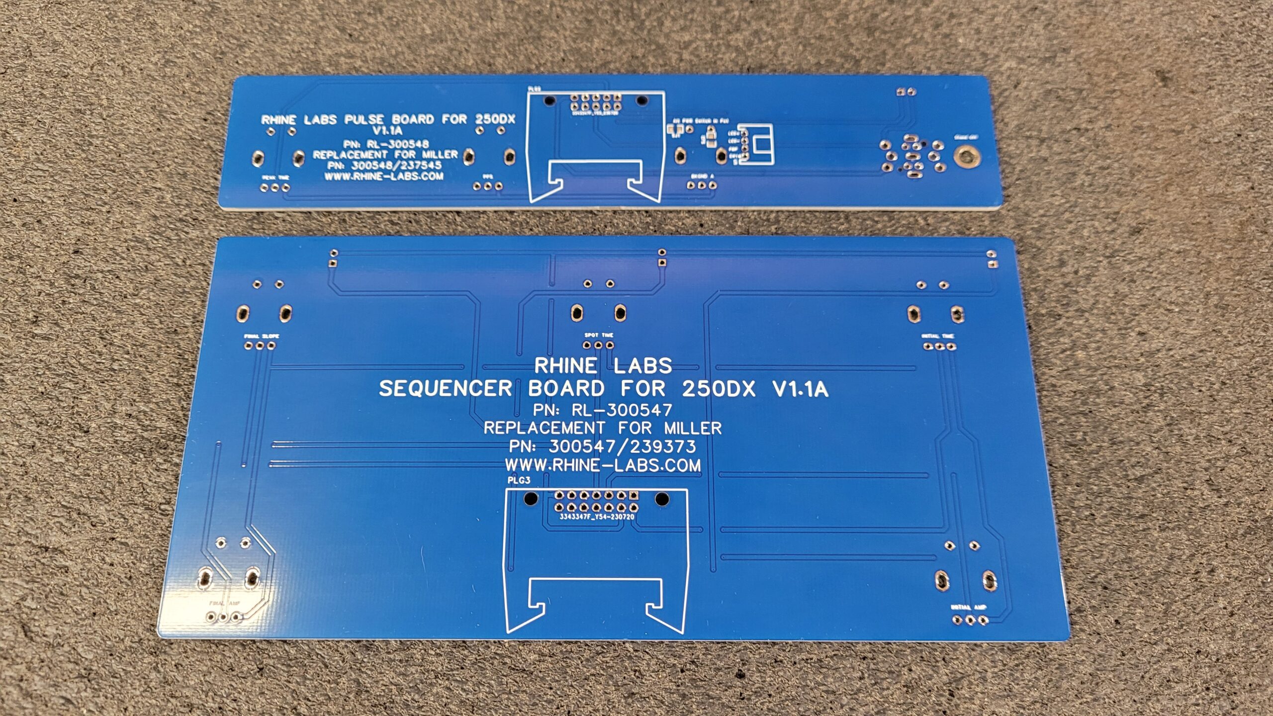
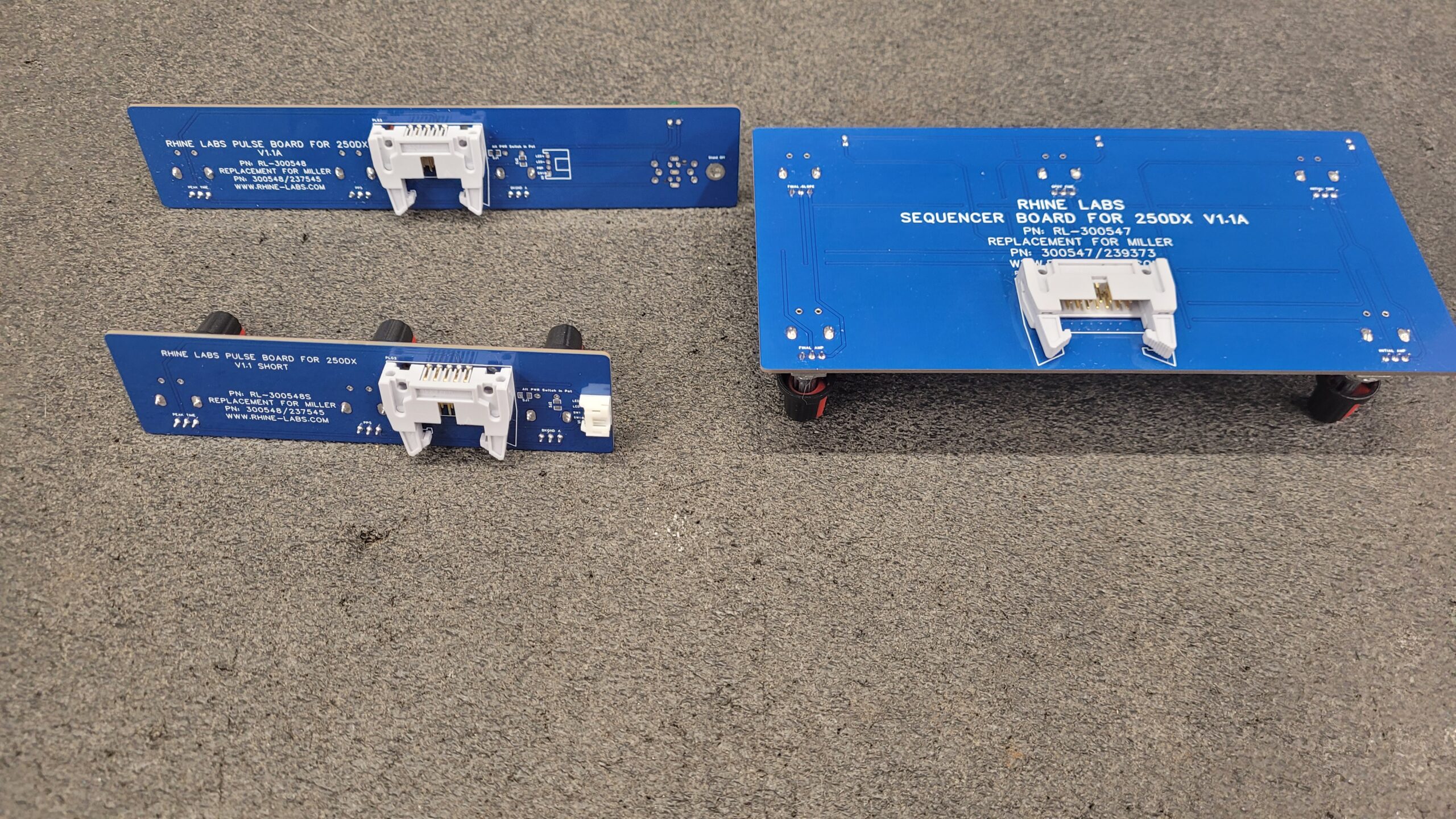
- IDC Connectors: “Horn Buckle Type In White” – 10-pin: 230-011-810-209 / 14-pin: 230-011-814-209.
- Switch Push Button: Either ALPS SPEF110200, FP11SPA1B1TP00 or a Sub Momentary Mini Toggle: SH T8014A- Z1 12mm aka 15/32 Bushing.
- Optional 4 Pin 2mm Pitch PH Series JST Connector: S4B-PH-K-S(LF)(SN) for use with a different switch/LED setup.
- Optional 2 0805 Jumpers if using the PRS11R-415F-s103B1 with an integrated switch at R1-3.
- Knobs: The specific type of knob will vary depending on the potentiometer chosen.
- Push Button Actuator: This will be 3D printed to meet the project’s requirements depending on power switch method used.
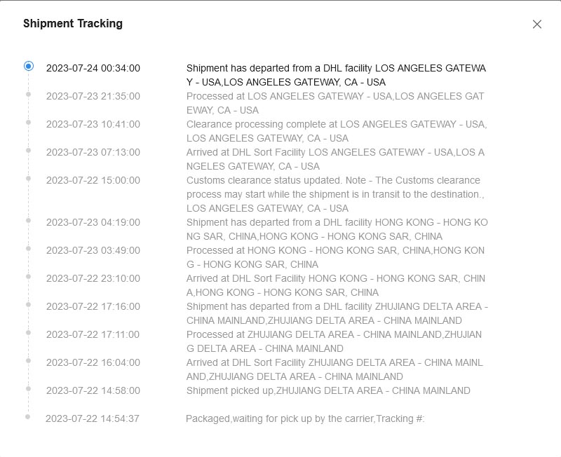
As I woke up on this Monday morning, July 24th, I was pleasantly surprised to learn that the circuit boards have already arrived in Los Angles, which is fantastic news. However, my excitement was slightly dampened by the realization that the parts required to populate the boards have not yet been shipped from the supplier. It appears that I might be facing delays due to what seems like standard delays or unfulfilled promises from the supplier. Worse is i may have to order from another source. It is a common practice for overseas suppliers to initially promise the availability of stock but experience delays due to an insufficient quantity or a single back-ordered item. Instead of contacting buyer they wait.
While it’s normal to encounter such supply chain setbacks, I will remain optimistic and proactive in addressing the situation. I’ll take this opportunity to reach out to the supplier for updates and ensure that the parts are shipped promptly. In the meantime, I can use this extra time to get other things around the ship done and make necessary preparations for when the parts do arrive.
Patience and perseverance will be key during this phase, I’ll make a conscious effort to stay focused on the task at hand and keep but and I’ll continue to stay on top of the parts situation to minimize any further delays. Once the parts arrive, I’ll be one step closer to bringing my project to fruition, and I’m eager to see it all come together.
Wow! DHL delivered my package two days early, and JLCPCB impressed me with their incredible speed. From the time I placed the order to the delivery, it took less than one week. I wish the parts house could be as fast.
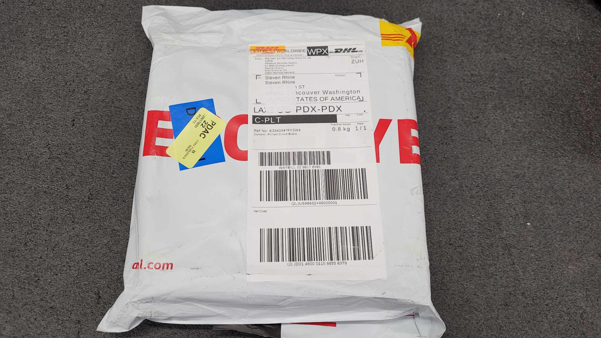
Unboxing Video (9:30AM Pacific Time 07-28)
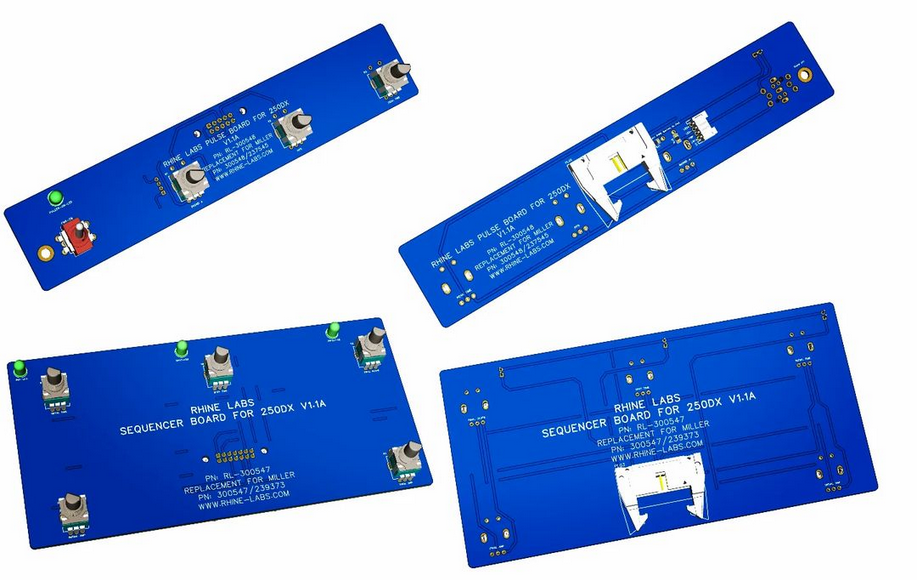
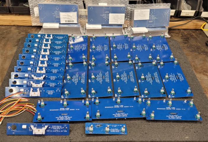
After a few days I Eventually had the time and Unboxed The First Lot of the Miller 250DX DIY Pulse 300548 / Sequence 300547 Upgrade Prototype Boards.
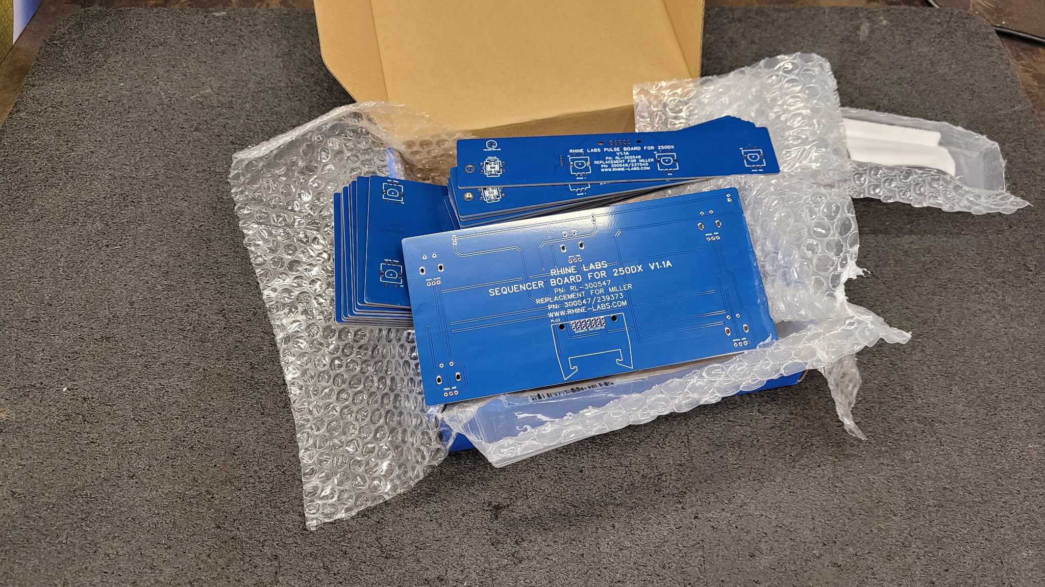
The First Lot of 10 Boards.
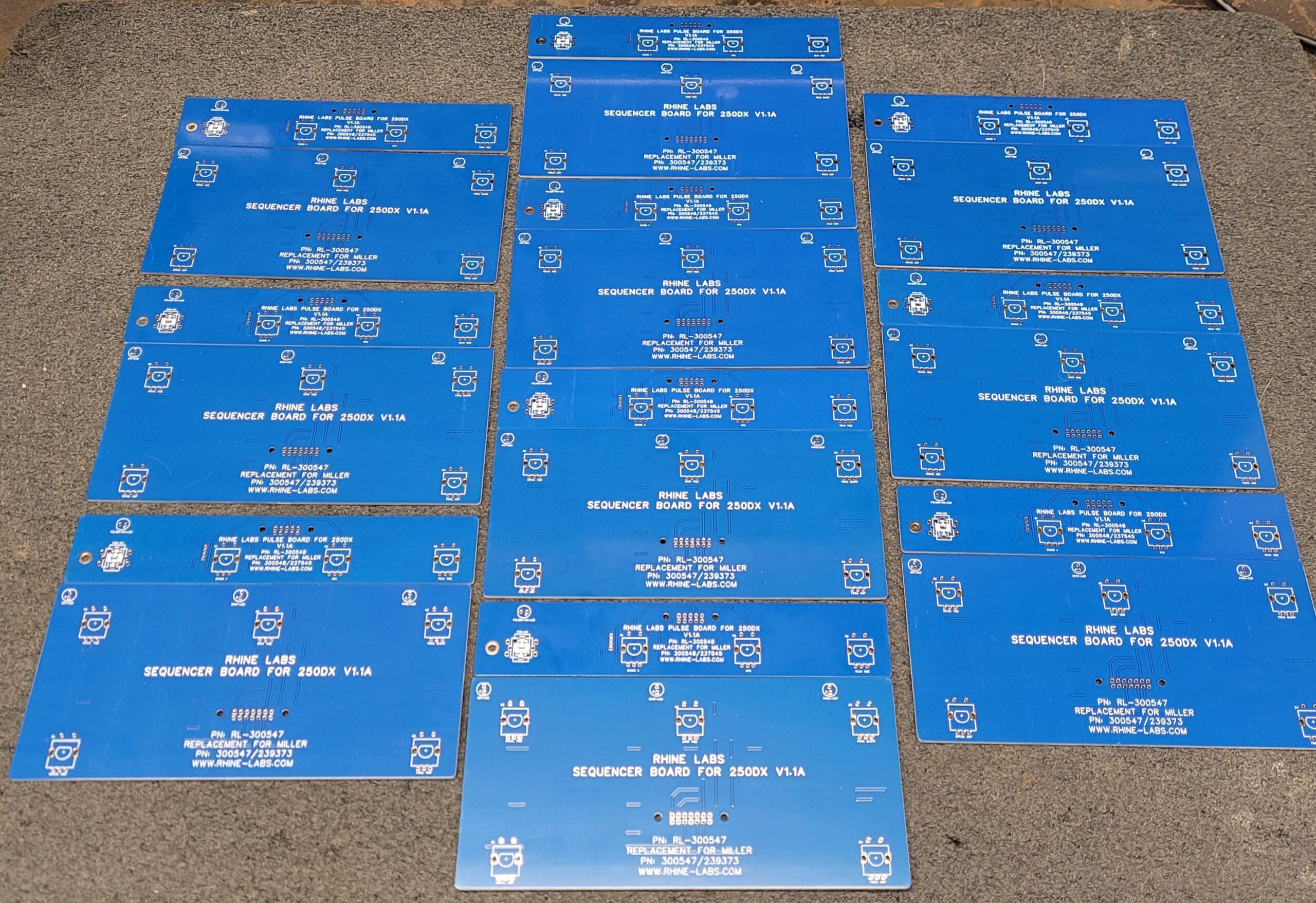
Front and Back of the DYI Miller 250DX Pulse and Sequencer Boards Awaiting Parts.
Tracking Update on the Pot’s Est. Aug 14th Ughhhh hope they Arrive Sooner than expected! Prob Not its Friday there and carrier will not pick up till Monday.
As I am Waiting on the slow boat that has the proper parts. I Found some random encoders with the proper footprint and bushing diameter and I did some Test fitting all is looking well.
Boards are Not Mounted just hanging There for a Photo Op and The Pots I will be Using Arrived.
I assembled a Pulser PCB was gonna test and well. Murphy Stuck Again.
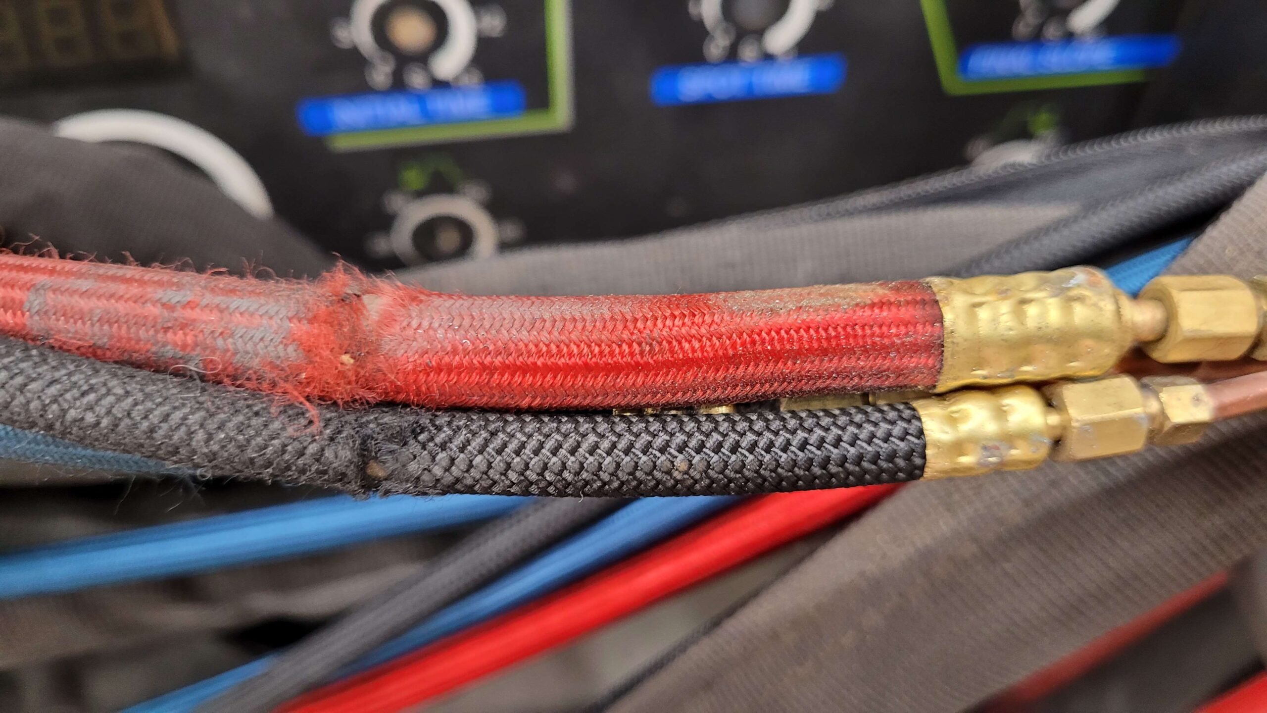
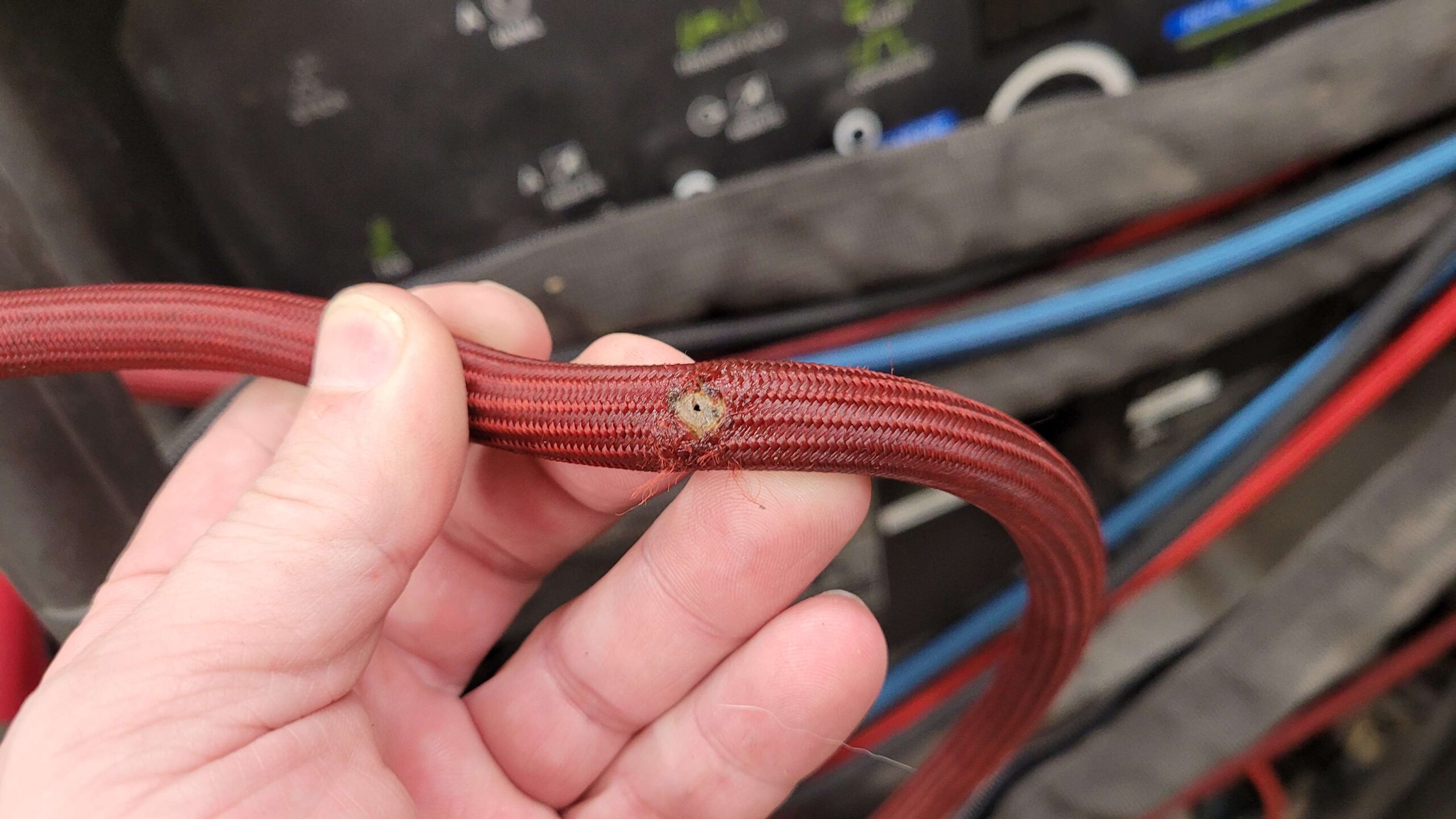
Torch Sprung a Leak I guess my torch lines need serviced LOL!!
More Later!
Some Parts Arrived Aug 14th!
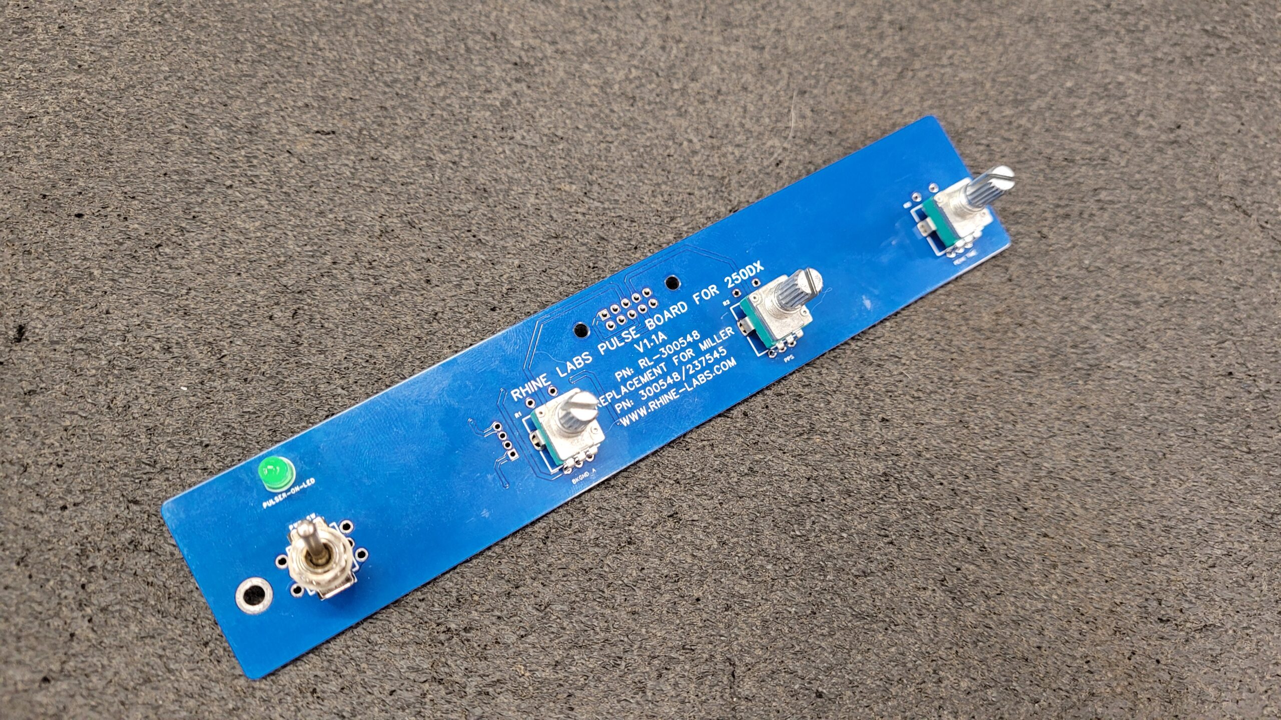
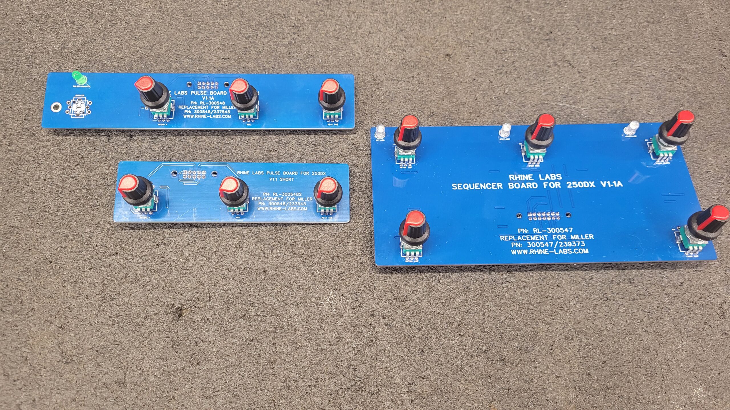
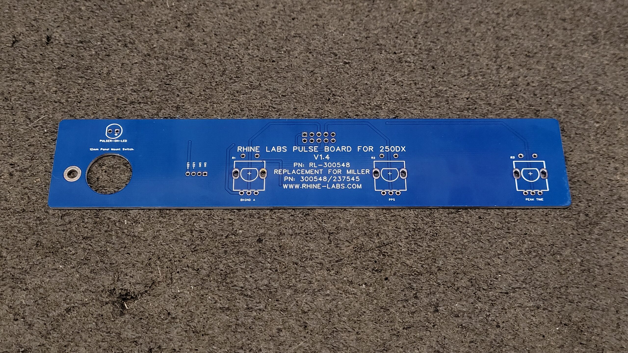
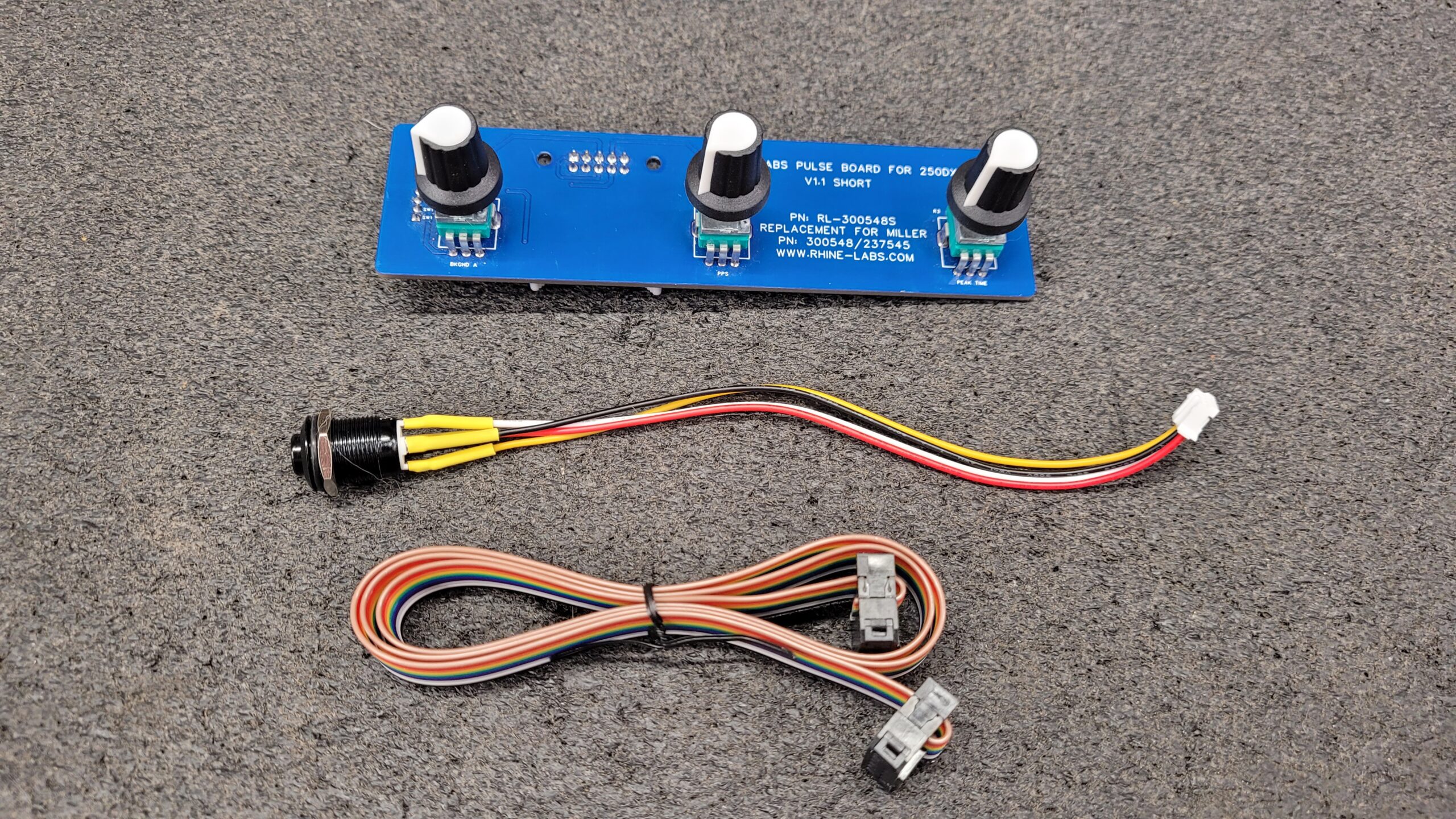
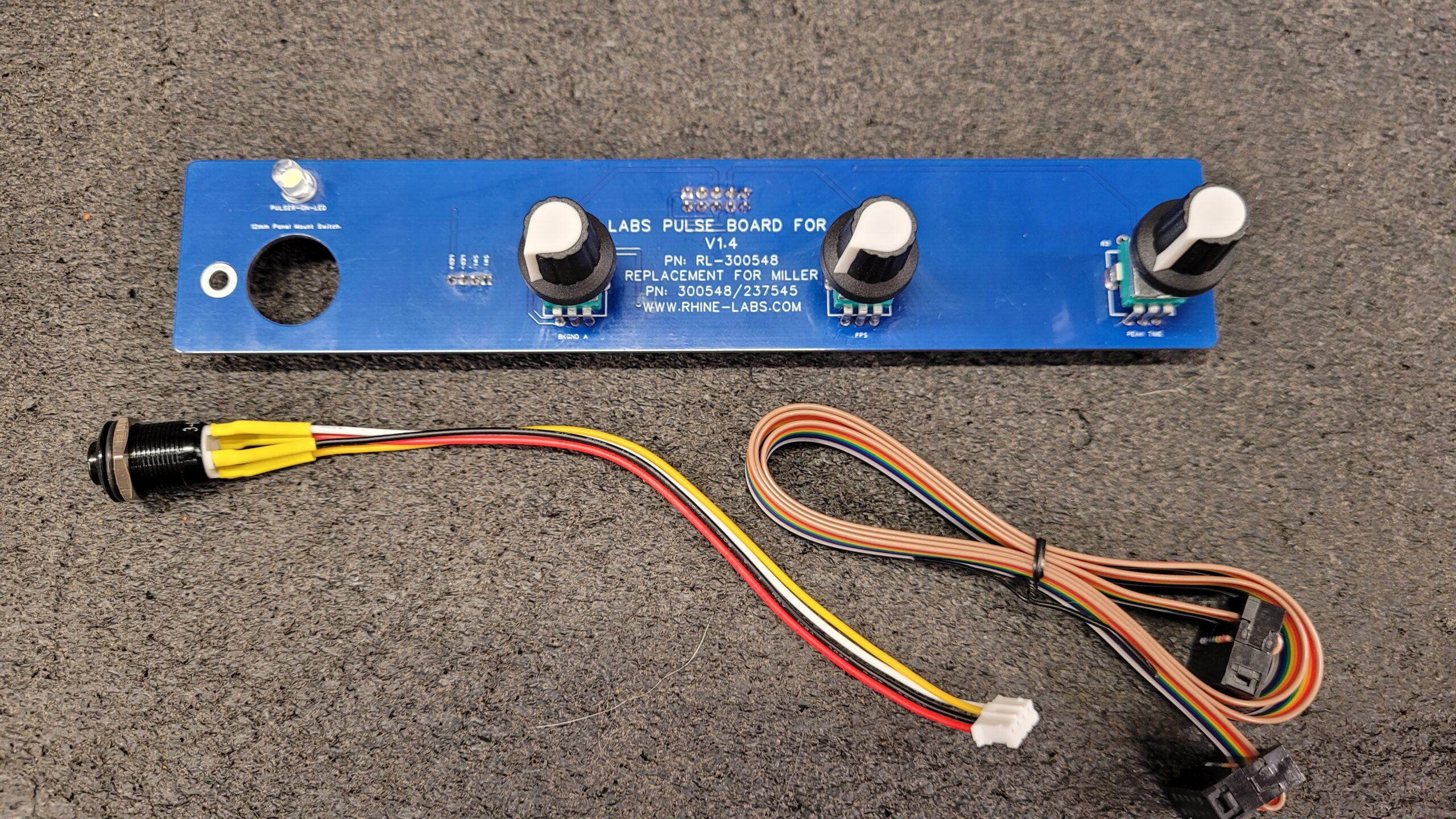
Here is Rendering of Proposed Rev 1.3A/4… Anyways, I blew a line on my tig torch and went way over budget on sourcing white IDC Connectors wich ended up being china white / gray. I ran out of spare time! I do have rev 1.4 of the pulser board almost ready to send to board house which will prob be the final rev. I appreciate all the messages and suggestions, I have implemented some of them in to rev 1.3/4 I agree using a Separate 12mm Panel Mount Replaceable Power button/rocker switch that can be sourced at a local hardware or jungle store is the best solution. I initially did a short board for quick testing, The momentary toggle switch was not stable so all rev 1.1 boards will need to use an alternate method.
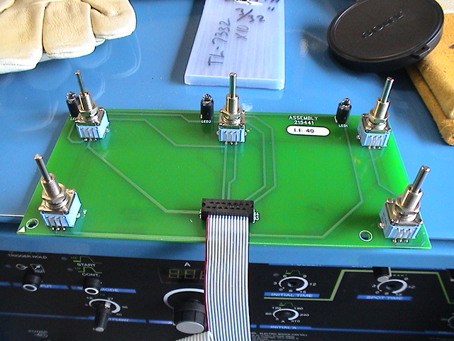
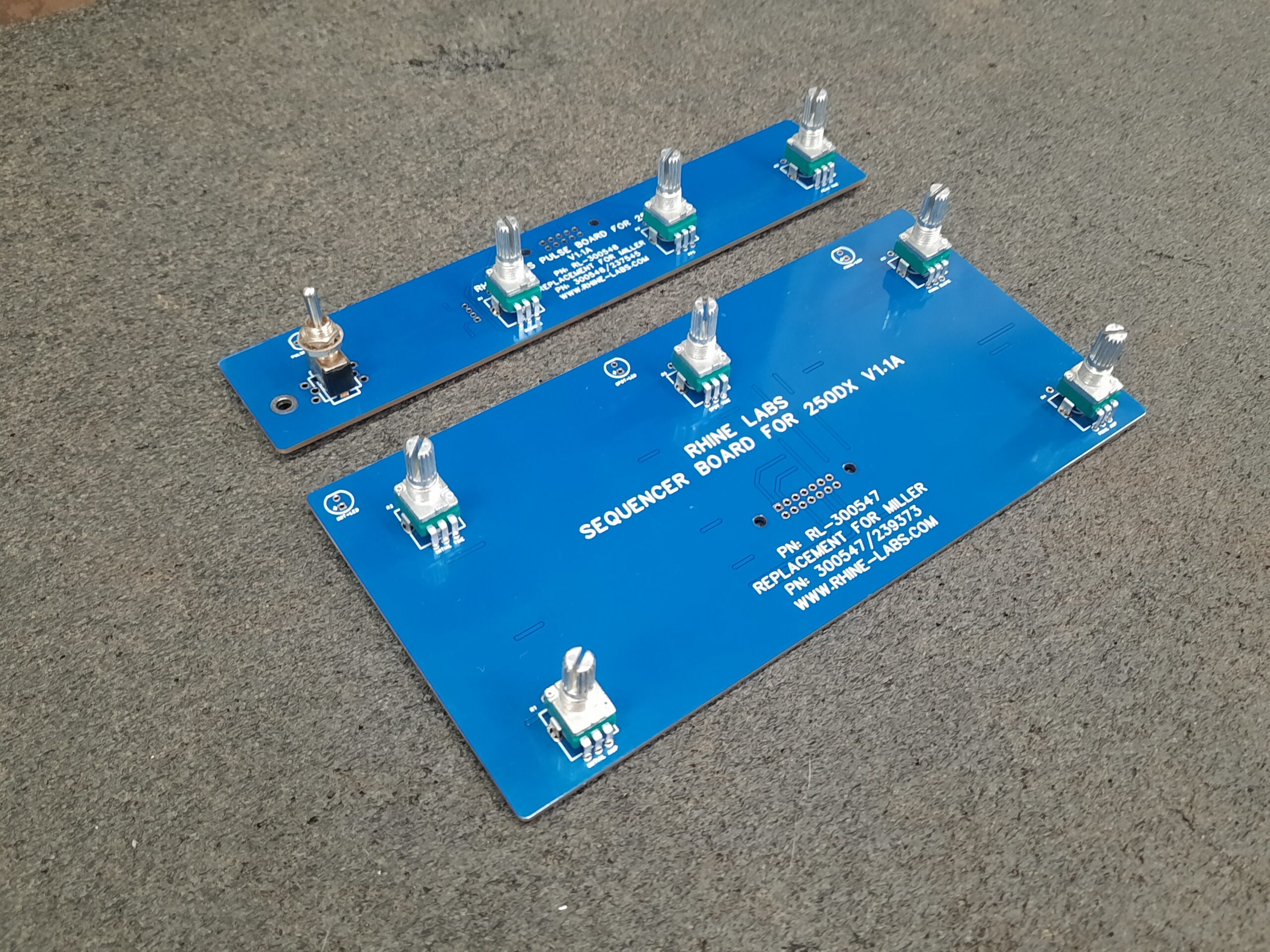
Here are Version 1.1 and 1.1 Short Assembled.
Options…
You Will be able to Use More Expensive 10K Pots With Integrated Momentary Switch at R1 for Power
Use a 12mm Panel Mount Momentary Push Button or Rocker with or Without 3V LED.
If using a switch with LED the LED on the Board is not needed.
September 07 I could not sleep spent about an hour playing with the PCB Hope to be ordering V 1.4 soon. I may let some V1.1 shorts go in to the wild if people want to beta test and experiment. I have messaged the ones that inquired wanting prototype boards.
I Will Update When I have some time, I know I need to replace my torch line but need to find some distraction free time.
Updated September 08 2023: Thanks to a Facebook Group Member He has an original Miller 250DX Pulse Board and a 1st Gen 250DX the Spacing on the Gen 1 250 DX is Confirmed Different. So My Boards Will only Work on the Newer Style Units. But I will solve this and make boards for the older units also. He has sent me all the measurements to implement on the next PCB revision or Board Order. I will try and get a Schematic and confirm pinout.
September 28th 2023
I have dispatched a few beta boards, specifically V 1.0 FJB’s, totaling 5 boards. Thus far, I have received no complaints, which is reassuring. In addition, I have sent out some V1.1A and Shorts. I Do have some remaining V 1.1A and V 1.1 Short boards, which were reserved by individuals who expressed interest but have not completed the payment process.
It’s important to note that my boards are compatible only with the newer machine models. Progress on this project is temporarily halted until the beta boards are successfully distributed and in use. Regrettably, the project has exceeded the initially allocated time and budget It was a hit and miss finding quality parts and reliable sources.
As a gesture of appreciation for the V1.0 FJB beta testers valuable feedback, all five beta board testers who participated in the V1.0 FJB beta testing phase will receive complimentary 1.3A or can wait for V2.0 retail boards once they are finalized and ready for distribution in exchange for the purple beta V1.0 FJB boards.
Anyone that made a Cash App Donation Prior to September 28th 2023 will be eligible for 15% off the Retail V2.0 Boards when available even if you made a 1.00 donation you get the thank you savings for your support.
December 3, 2023, All Purple/Red Beta Boards made with the fiber laser have been Received back and Destroyed. A Big Thanks to the Initial beta testers enjoy your V1.3A Pulser Boards. Now I am Revealing Rev 1.4, It Just Arrived I have ton do some QC Check! The Difference between 1.3A and 1.4 was minor parts fitment fixes, power switch hole changed to a larger round hole. The Next revision 1.4A/1.5 will be cosmetics as I forgot to add Plating on the Hole for the Power Button on rev 1.4 Oops, Some screen printing fixes. As Soon as I have the time I will assemble one and take a photo.
V2.0 Retail Boards Have Arrived. Watch the Unboxing.
Details and Pricing will replace the Beta Boards List Below when Available! Target Pricing will be About 1/2 of Millers Current Pricing. I am almost done with the shopping cart implementation to my rhine-labs.com website.
Want to Buy one Help Support this Project?
Assembled Beta Board Pricing: (Updated 03/26/24)
The V1.1 Short, V1.4, and V1.1A boards currently available are beta boards they are fully functional. These boards may have screen printing errors, they will include cables and knobs in random colors (all will match) mostly white knobs. If the knob color does not suit your preference, you have the option to order Standard 6mm knurled knobs of your desired color or shape you desire from Amazon or other source. I am trying to add a shopping cart or payment Links to my blog to make ordering simpler.
V1.1 Short Pulse Board Assembled with Cables 10pin Cable and Push Button W/LED. (SOLD OUT)
V1.4 Pulse Board (SOLD OUT)
V1.1A Sequencer Board (SOLD OUT)
Assembled Retail Board Pricing: (Updated 03/26/24)
V2.0 Retail RL-300548 Pulse Board (Pricing Soon)
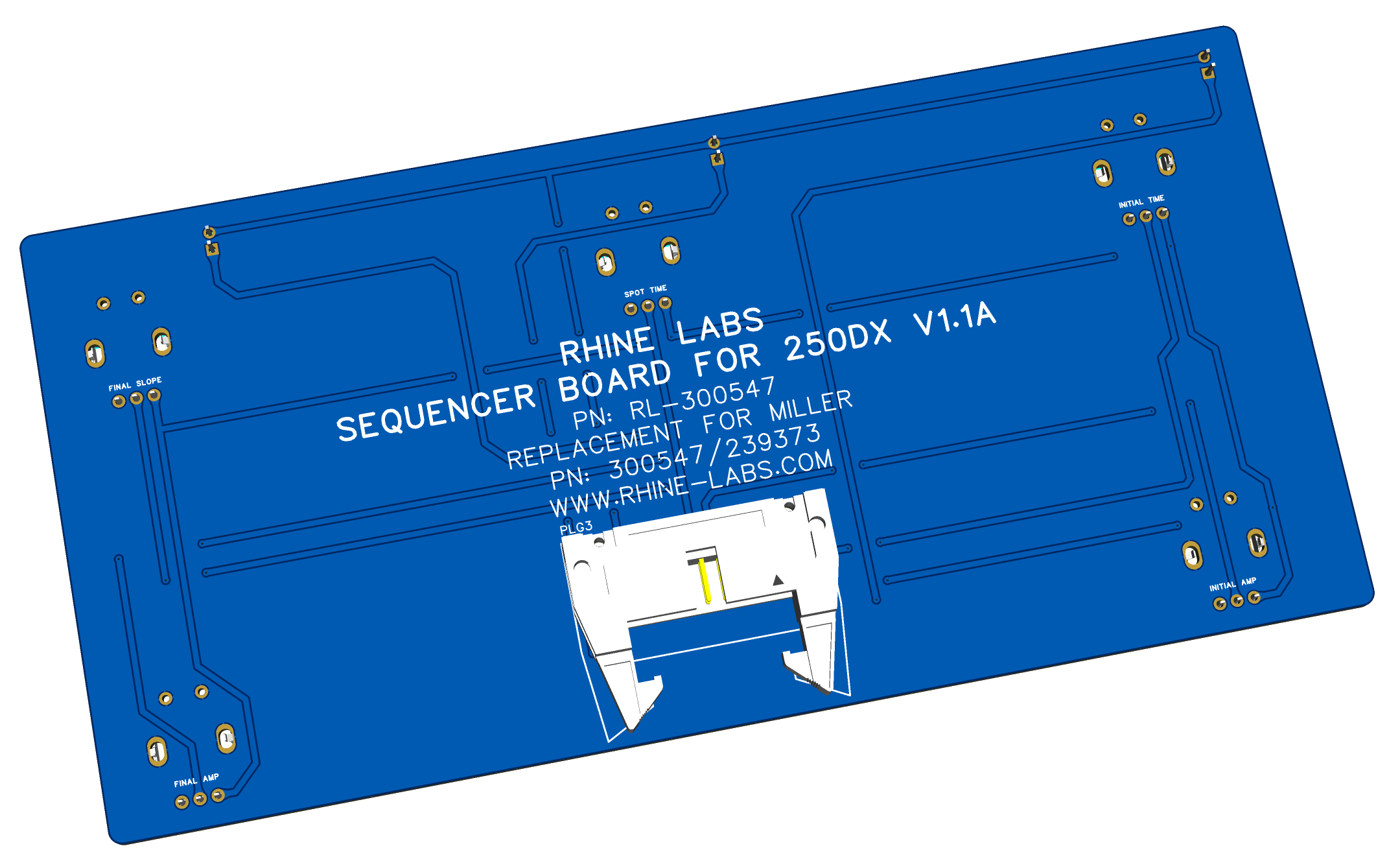
V2.0 Retail RL-300547 Sequencer Board (Pricing Soon)
V2.0 Retail Combo RL-300547 & RL-300548 Boards (Available As Of 03/23/2024) (Low Stock 01-2026)
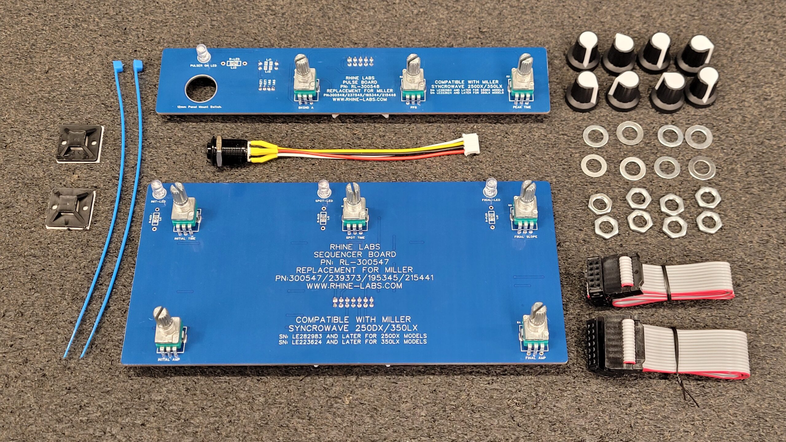
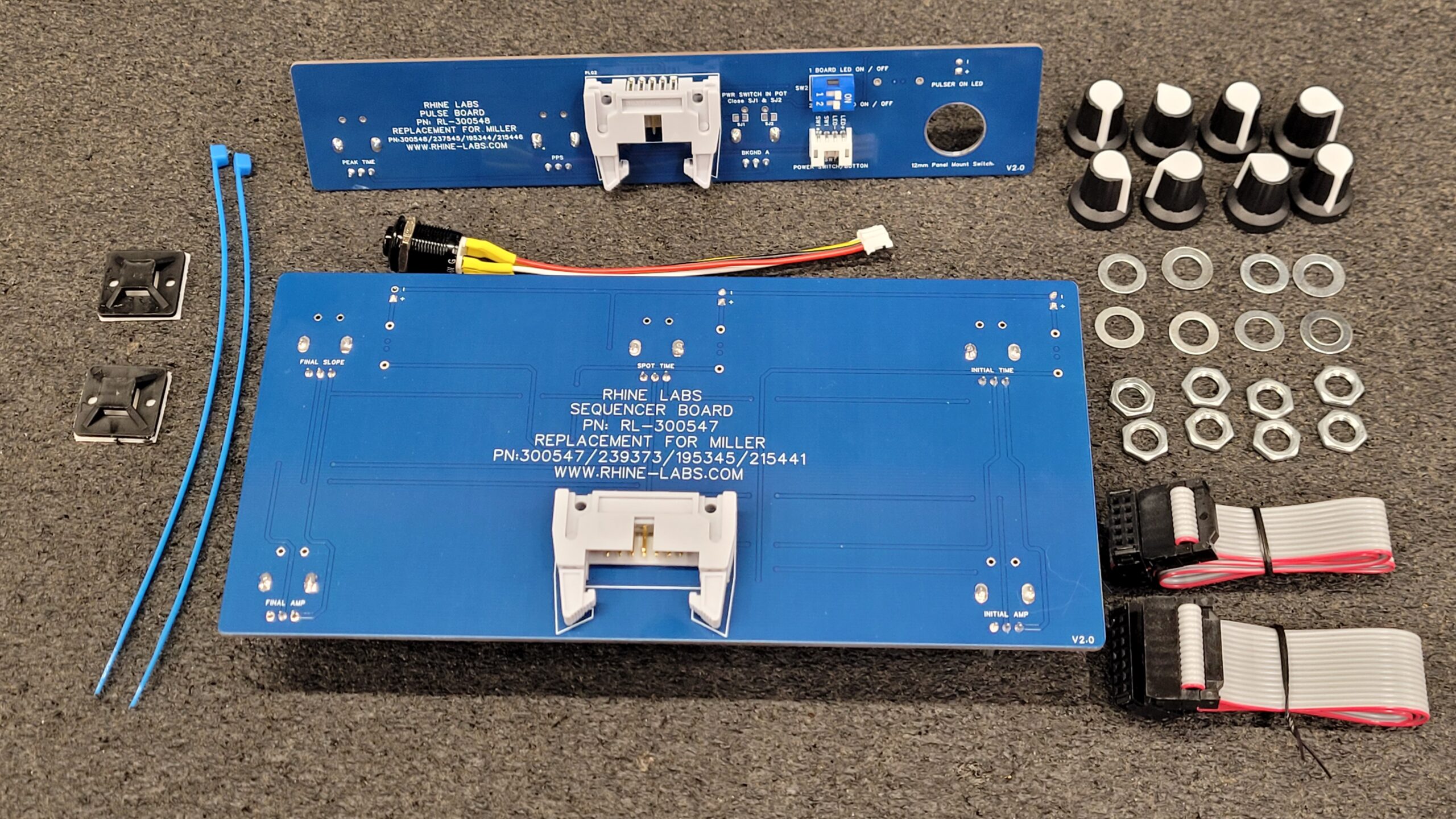
Assembly of the V2.0 retail boards Started as of March 9th and the first batch of V2.0 and V2.0L have been shipped to all that were on the list.
Compatibility:
RL-300548 Pulse Board, Replaces Miller Part Part Numbers 300548/237545/195344/215446 (Only) This will NOT REPLACE Miller Part # 190734 Boards
RL-300547 Sequencer Board, Replaces Miller Part Numbers: 300547/239373/195345/215441 (Only) This will NOT REPLACE Miller Part # 190738 Boards
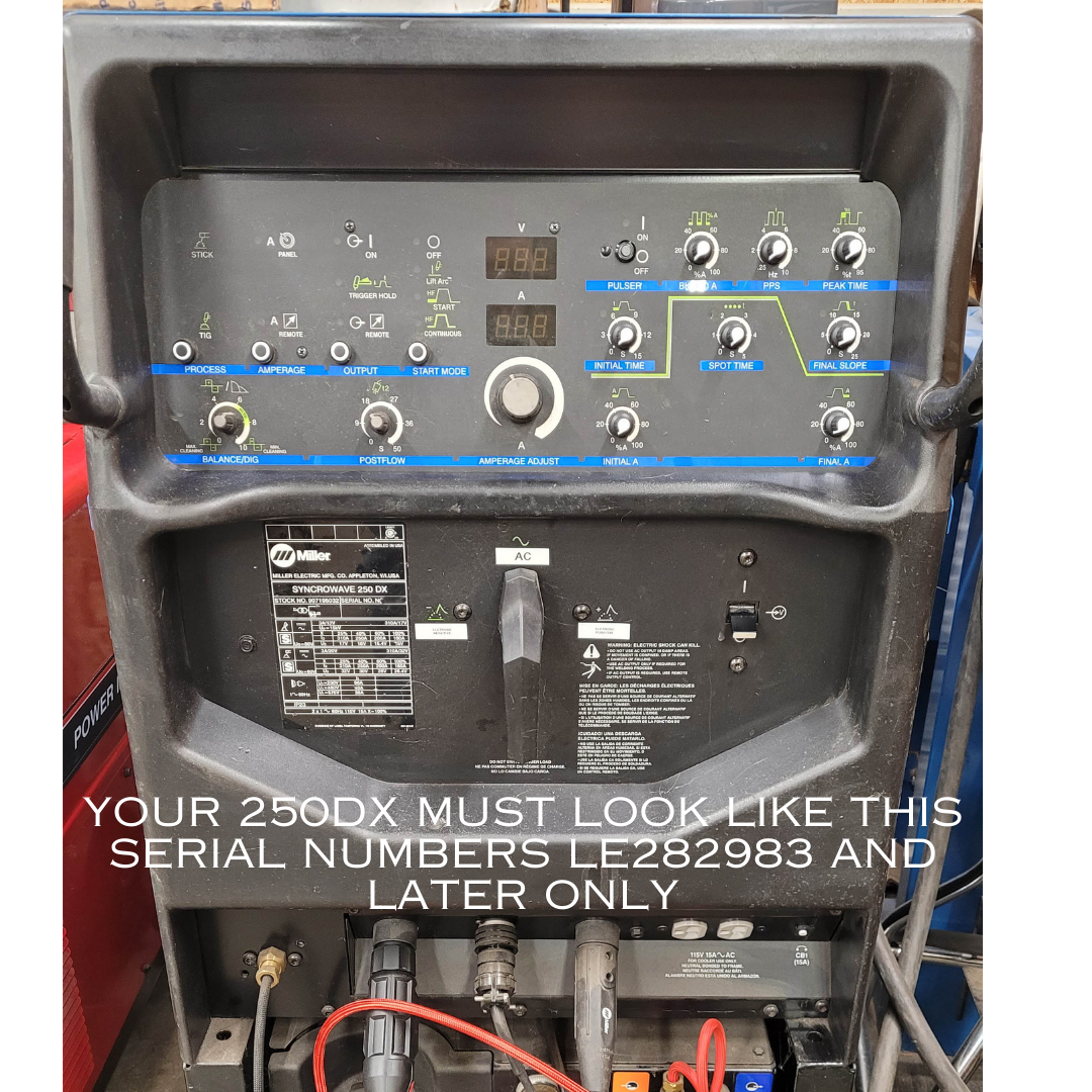
These Boards will only work with Serial Number: LE282983 And Later For 250DX Models Serial #: LE223624 And Later For 350LX Models.
Please Verify Your Serial Number and Part Number Listed in the Miller Owners / Parts Manual for Your Specific Machine Prior to Buying. You can find your manual for your welder at https://www.millerwelds.com/support/manuals-and-parts Any Compatibility Questions Please message me your machine Serial Number I will check for you.
For shipping within the US, there will be a flat rate of $15.00 for insured mail. Payment options include Cash if local, Checks, Money Orders, Cash App, or Credit Card payments. If you are outside of the USA Contact me for Shipping rates all International shipments will be paid via bank transfer.
You can Call Me or Leave a Text Message 360–567–6646 Text Message are Best. (This is a public facing number calls and text message only that means no photos or media) if you wish to send photos or media I will text you a different number or you can e-mail them to me (web @ stevenrhine.com or web @ rhine-labs.com) remove the spaces.
Some Installed Photos
V1.1A Pulse Board (Toggle Switch)
V1.1 Pulse Board Short
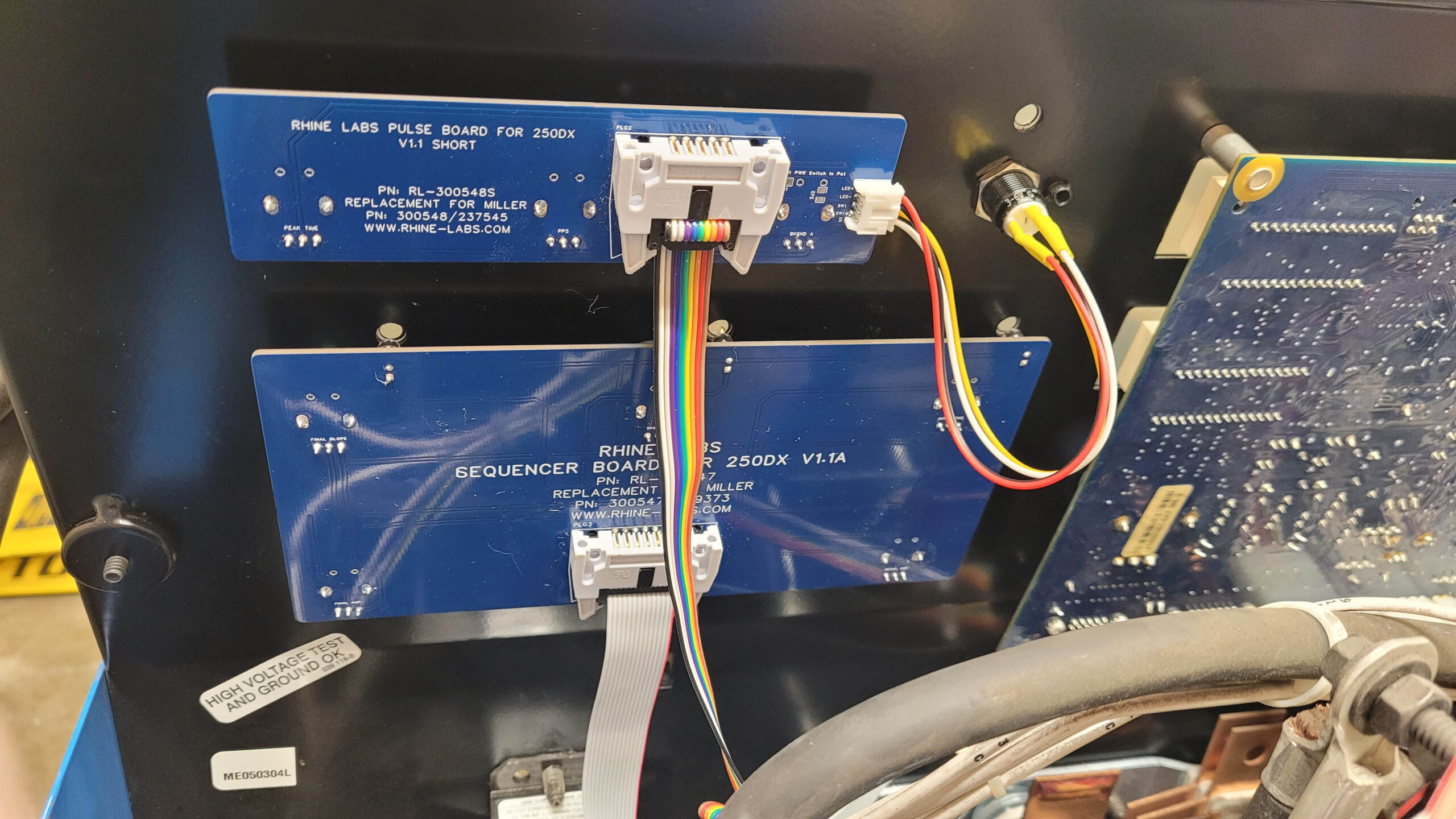
V1.4 Pulse Board (Retail Beta) / 1.1A Sequencer Remote Mount Push Button You Can Still use a Panel Mount Momentary Toggle if Desired.
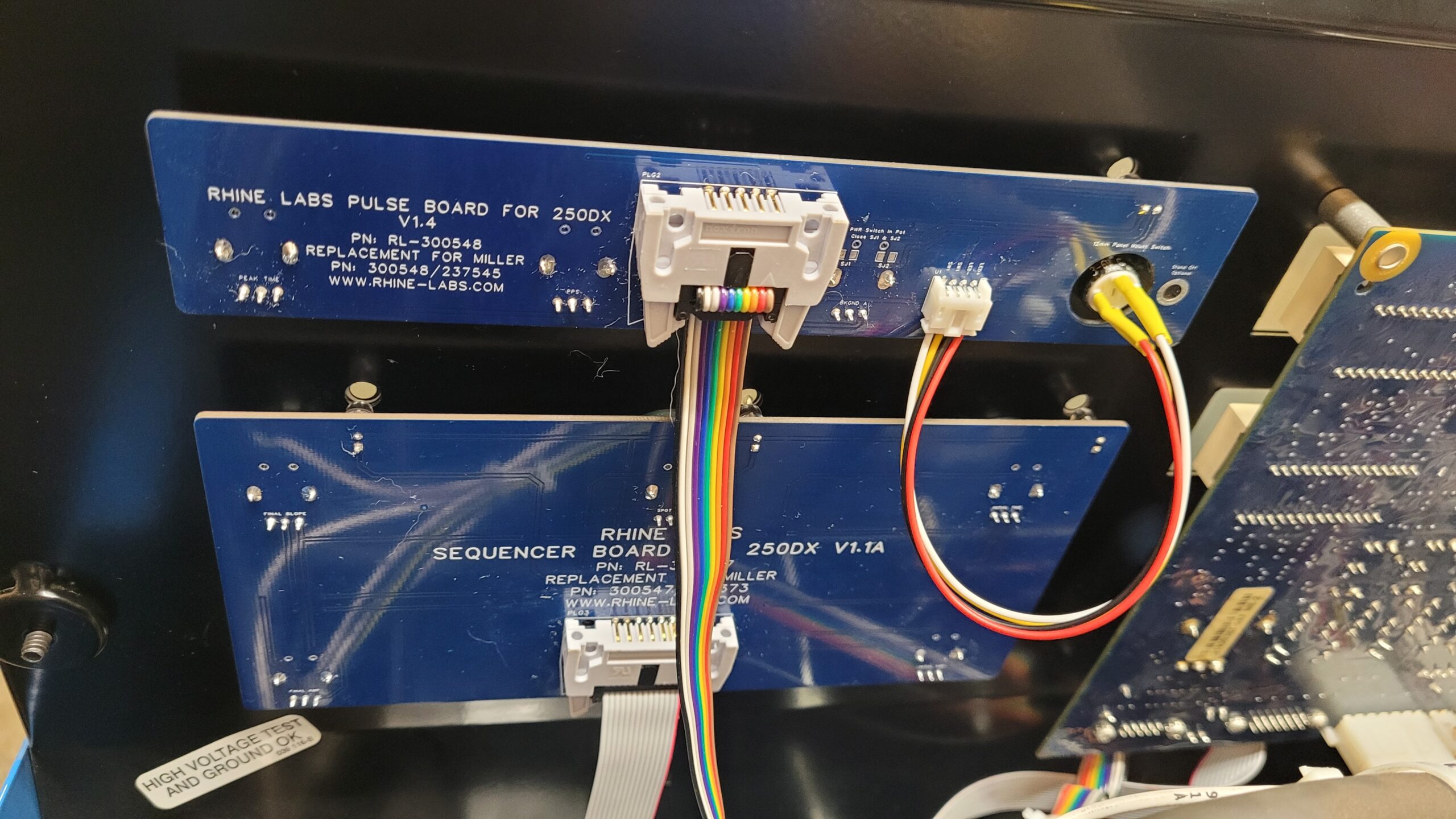
All Boards Now Have Green LED’s
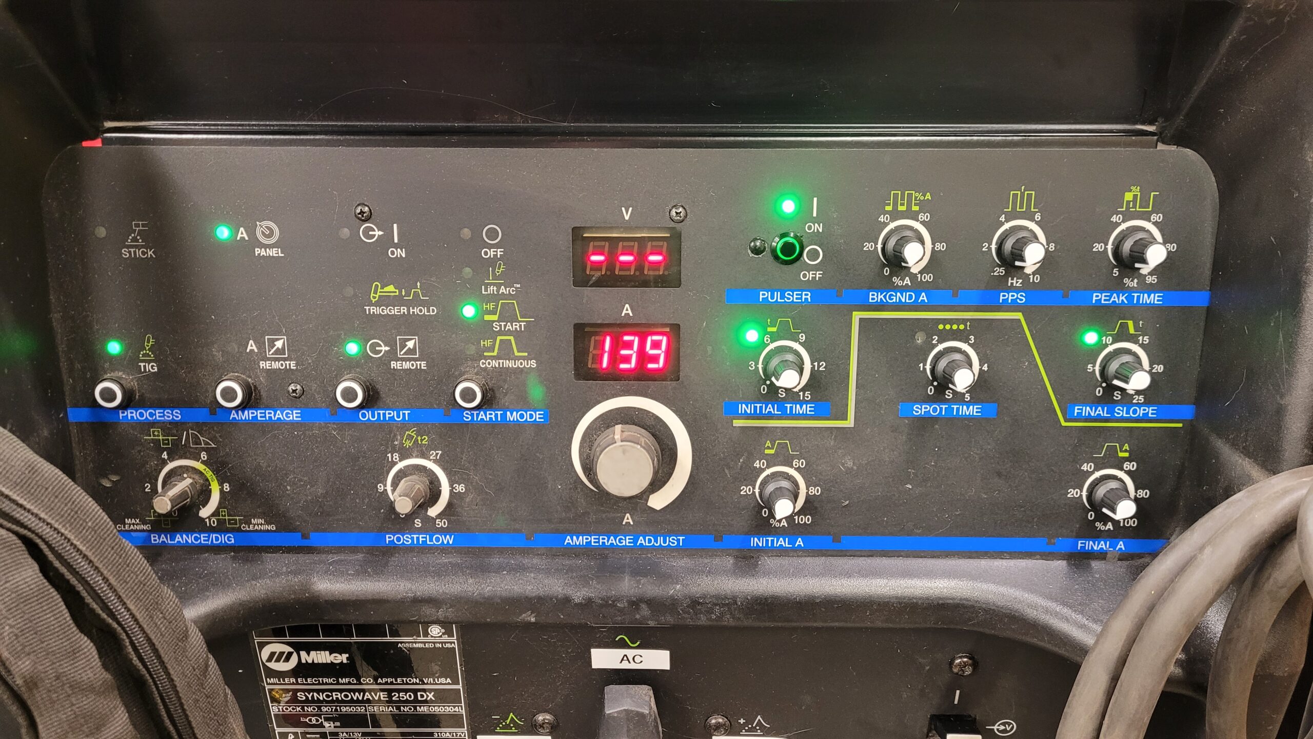
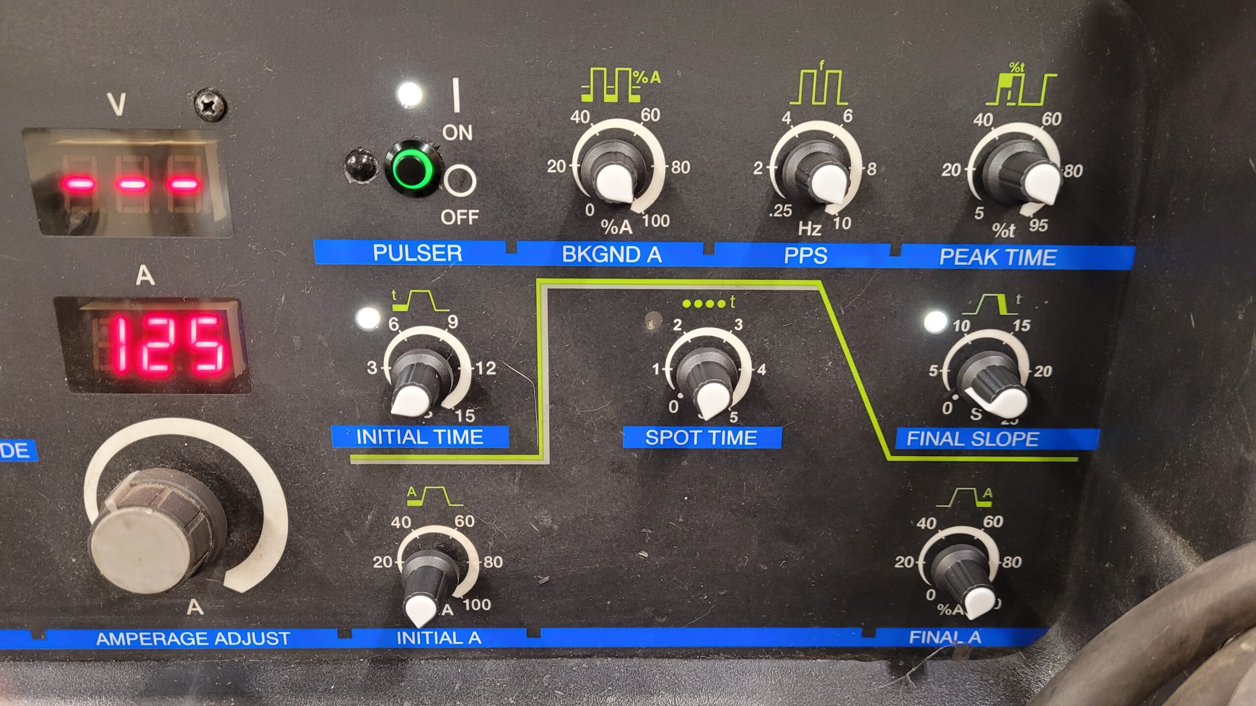
Operational Video (Not Welding)
Final Thoughts, The Retail V2.0 Boards will Be Available some time in the future Est. End of March or st of April 2024 in Fully Assembled Form Only. The Goal has been met having a lower cost alternative pulse and sequencer board that can use all common readily available parts.
Feb 2024 Discontinued Miller 250DX Tig Welder PN: 190734 (Pulse) & 190738 (Sequencer) Boards Build Post for the Older Flat Face 250DX Tig Welder Can Be Found Here
Last Updated on June 10, 2026 by Steven Rhine
[…] Miller 250DX Pulser Sequencer Build 2023 […]
[…] Feb 2024, The response for the initial pulse and sequencer boards has been better then expected, the Demand for the older Miller 250DX units has also been heavy. So, I decided why not make some for the older units that take the Discontinued Miller Part Numbers 190734 and 190738. If You need Boards For the Newer Miller 250DX See The Original Miller 250DX Pulse Sequencer Build Post. […]
[…] Miller 250DX/350LX Pulser and Sequencer Project Legacy Miller 250DX Pulser and Sequencer Project […]
[…] initially settled for an Cami Research Cableeye M2 just to test the cables I ordered for the Miller TIG Welder Pulser and Sequencer Boards. However, I’ve been on the lookout for a more comprehensive way to test resistance and diodes in […]