Xeltek Superpro 7000 Universal Programmer Teardown And Info. (Click On Images to See Full Size) and Quick Analysis.
(Note: The Xeltek EX Adapters are Discontinued By Xeltek No New Ones. Available on the Used Market Only)
I Will be Updating this page Since no schematics will need to slowly reverse this one section at a time as time allows me to mess with it.
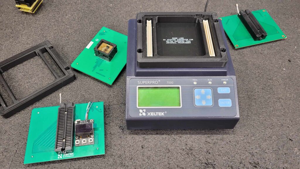
I have Started an EX to GX Adapter Converter Project
I recently added this chip programmer to my Xeltek chip programmer farm, with the hope of increasing my throughput and possibly acquiring some gang adapters that are available for it. Unfortunately, the unit was purchased “as-is” and was only checked for power-on functionality, but it seems to be experiencing a power supply issue.
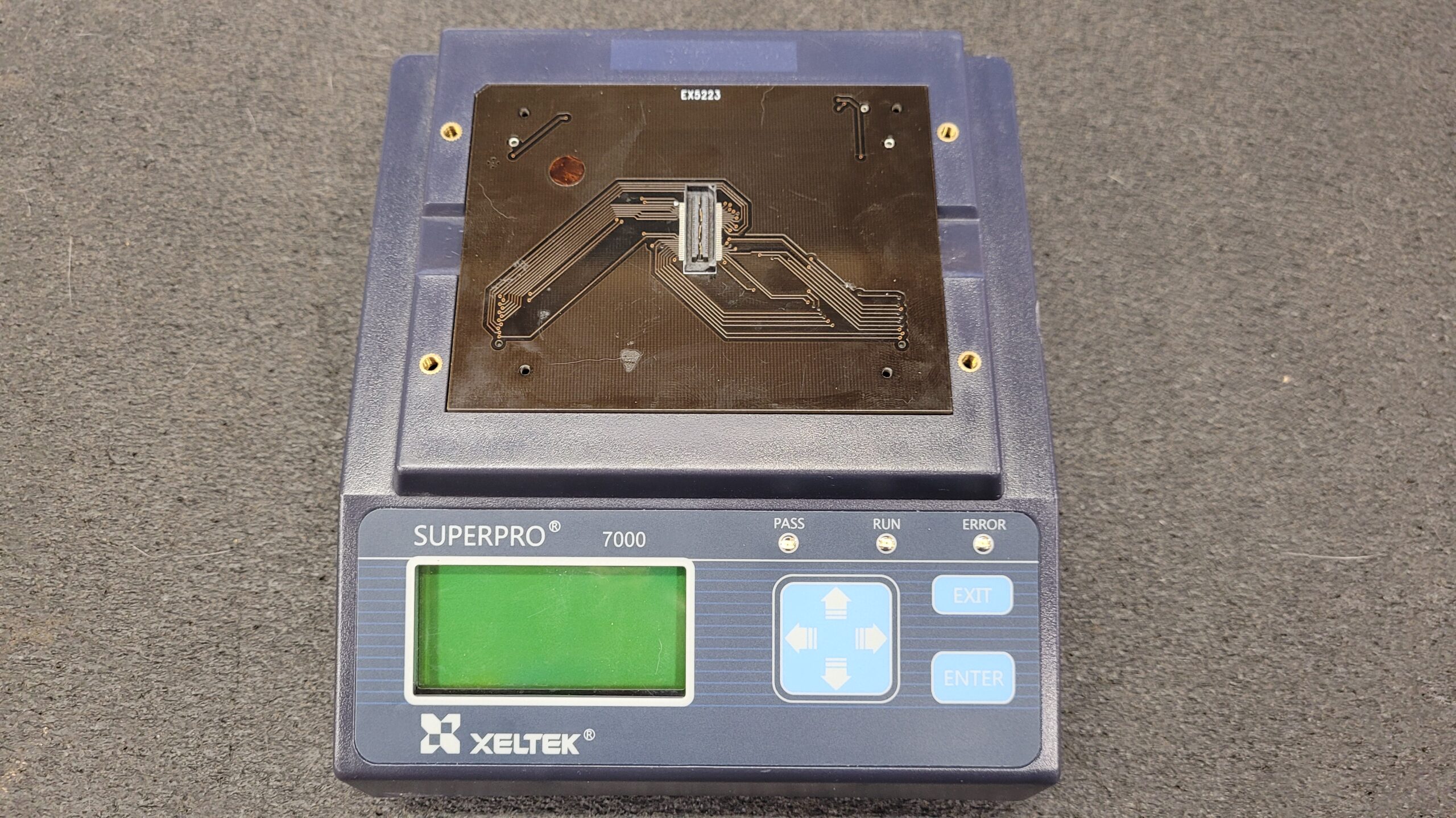
Despite this setback, I’m confident that I can address the problem and get this chip programmer up and running. With a little bit of troubleshooting, I’m hopeful that I can unlock its full potential and make it an asset to my programmer farm. This included the GX5223 with the MIPI 60-pin System Trace (STM) emulator connection.
Do you like this content? If so consider making a donation via Cash App $slrhine so I can get more available time to do posts and videos like this.
09/13/2022 I will try and get my notes added soon I have spent a lot of time on this already!
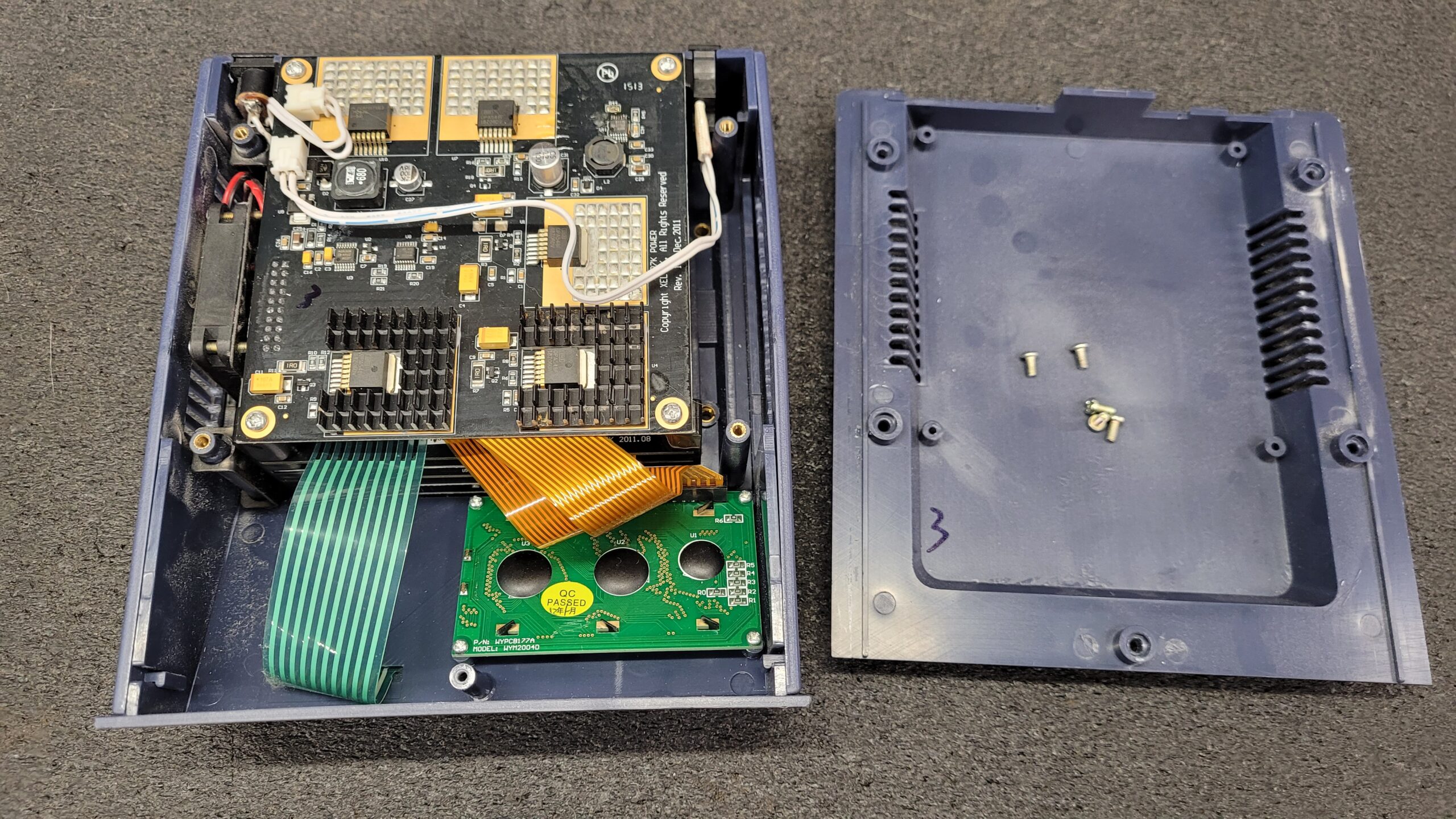
If you want to access the inner workings of the Xeltek Superpro 7000, all you need to do is remove five screws and lift off the bottom cover.
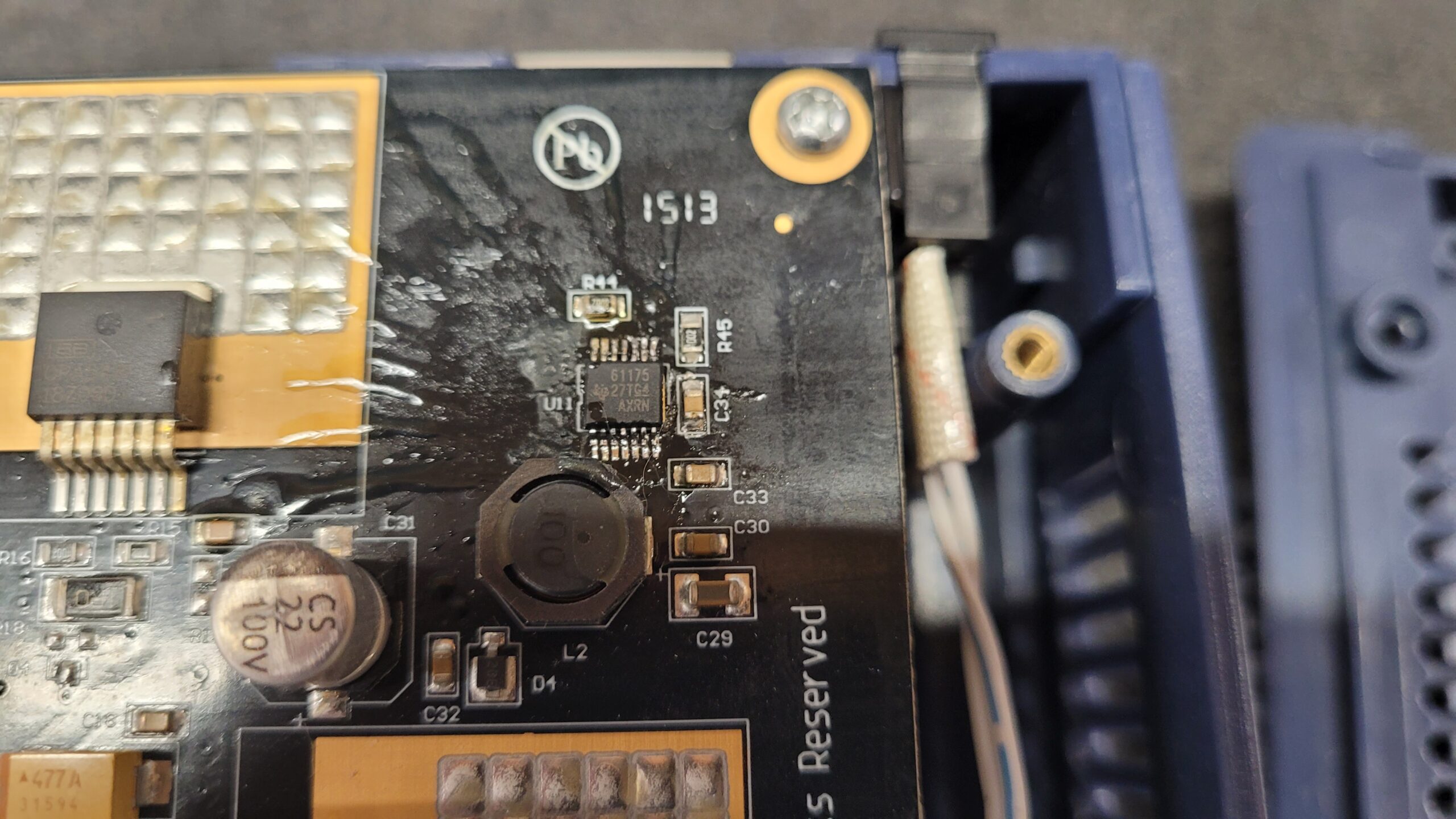
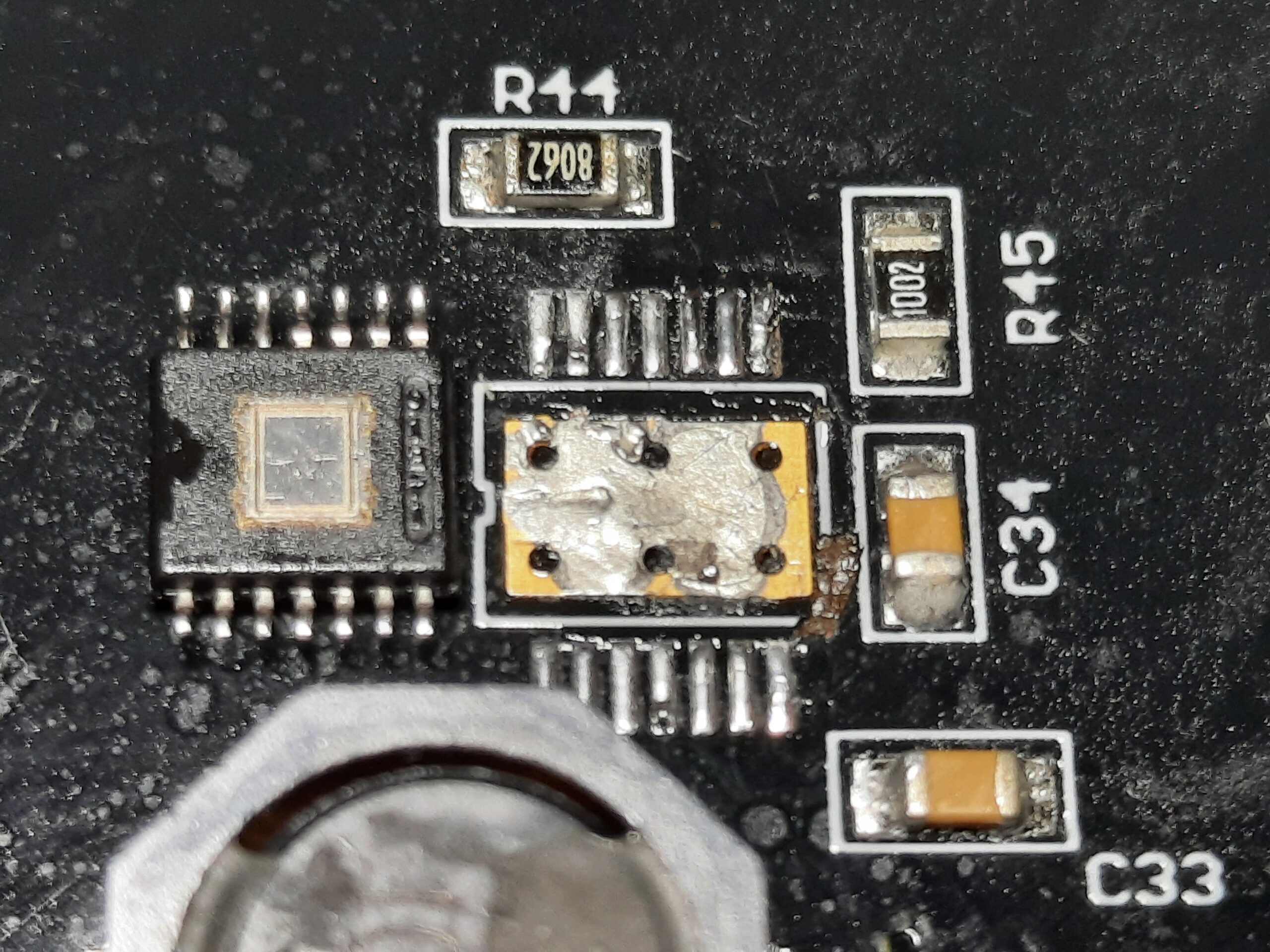
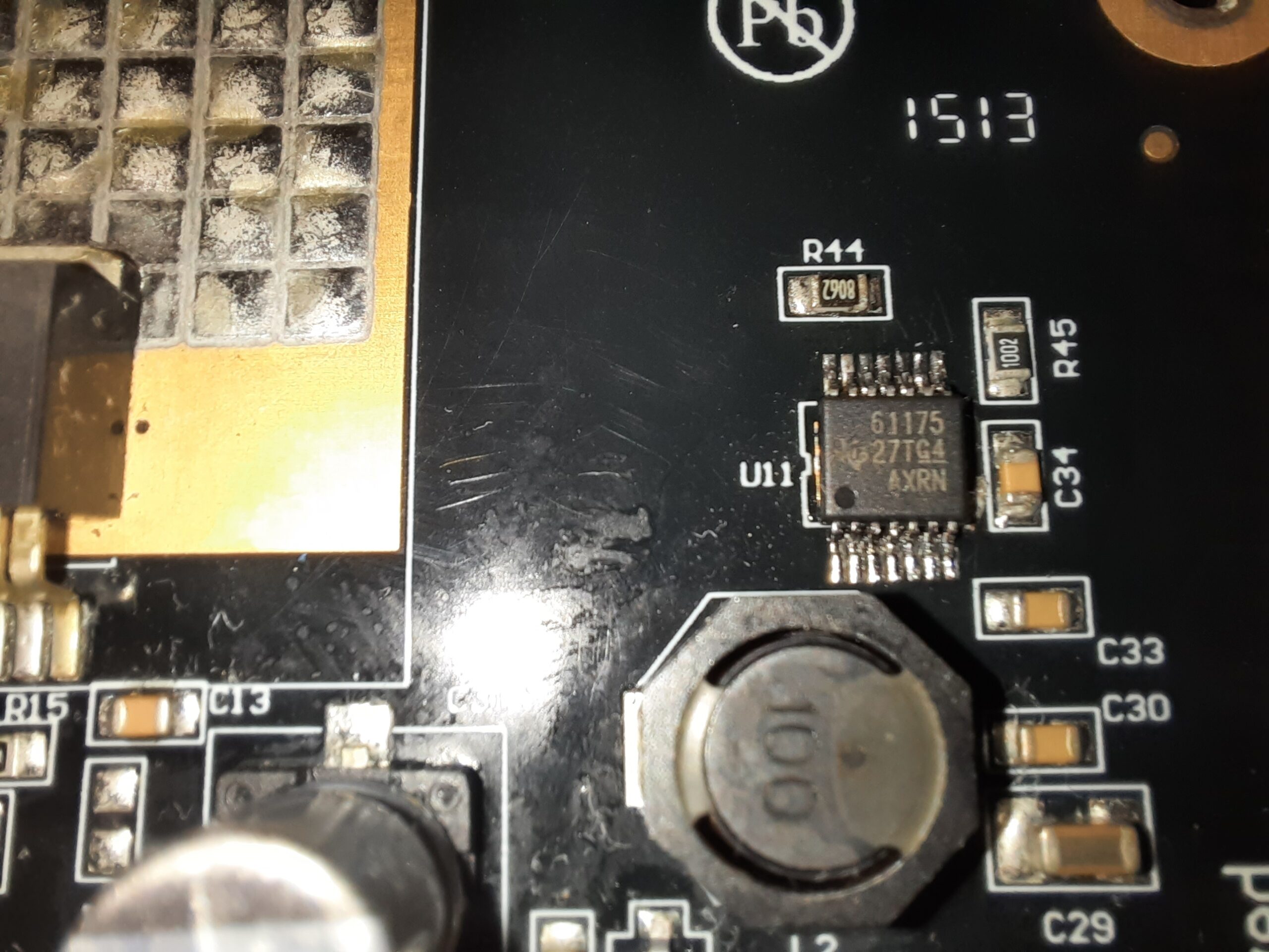
However, it quickly became apparent that this device has undergone repair work around U11, a TPS61175 3-A high-voltage boost converter.
It’s difficult to say for sure what caused the issue. It could have been a post-production repair at the factory, an attempted repair by an end-user, or simply a part failure. Regardless of the cause, it’s clear that there’s more investigating to be done.
Despite the uncertainty, I’m eager to get to the bottom of this and get the Superpro 7000 up and running again. With a little bit of effort and a lot of attention to detail, I’m confident that I can solve this mystery and get this device back to working order and put to good use.
Clearly the pry marks on the Chip and Circuit Board by C34 the work was done by someone who did not know how to solder or was in a hurry! Without a Doubt The smell was the stinky unknown Burnt Flux. Ohh well, it is always a gamble when buying used surplus power on tested only equipment. You never know what issues might be lurking beneath the surface, just waiting to rear their ugly heads. I would bet this is not a factory repair sure don’t look like it unless it was done on the 6th day in the 11th hour of the Chinese work week. Obviously it is a Botched repair attempt. I will remove the chip clean it up properly solder it back in place and make it look good.
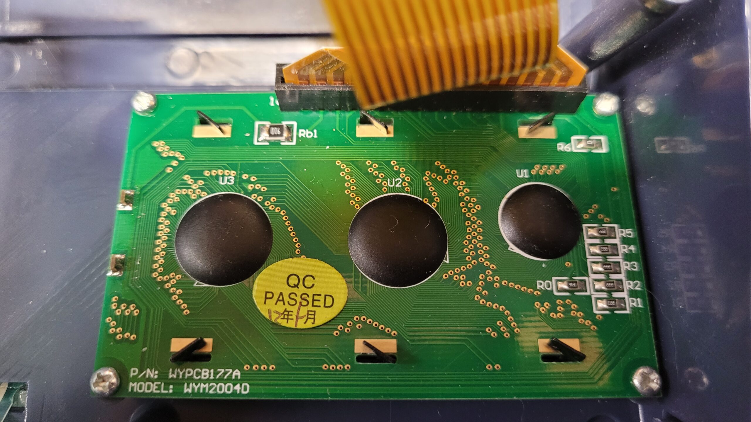
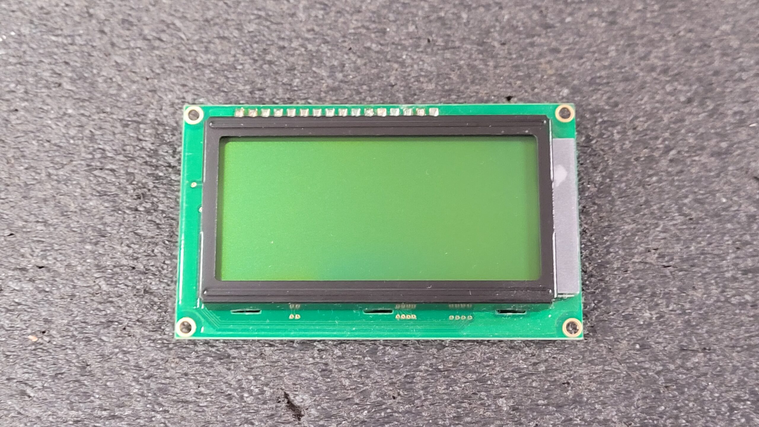
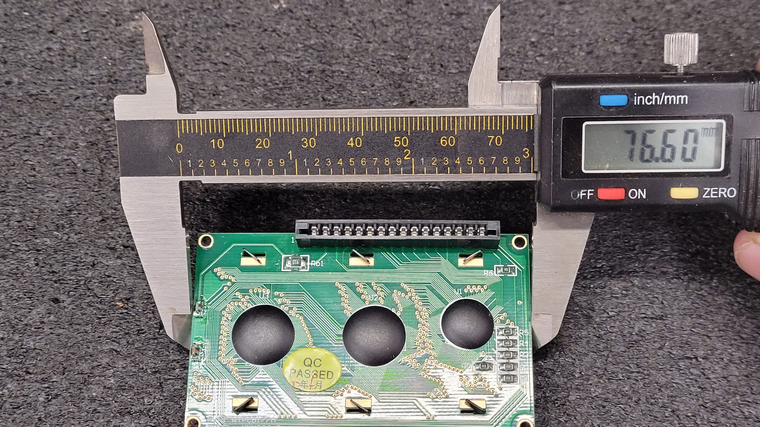
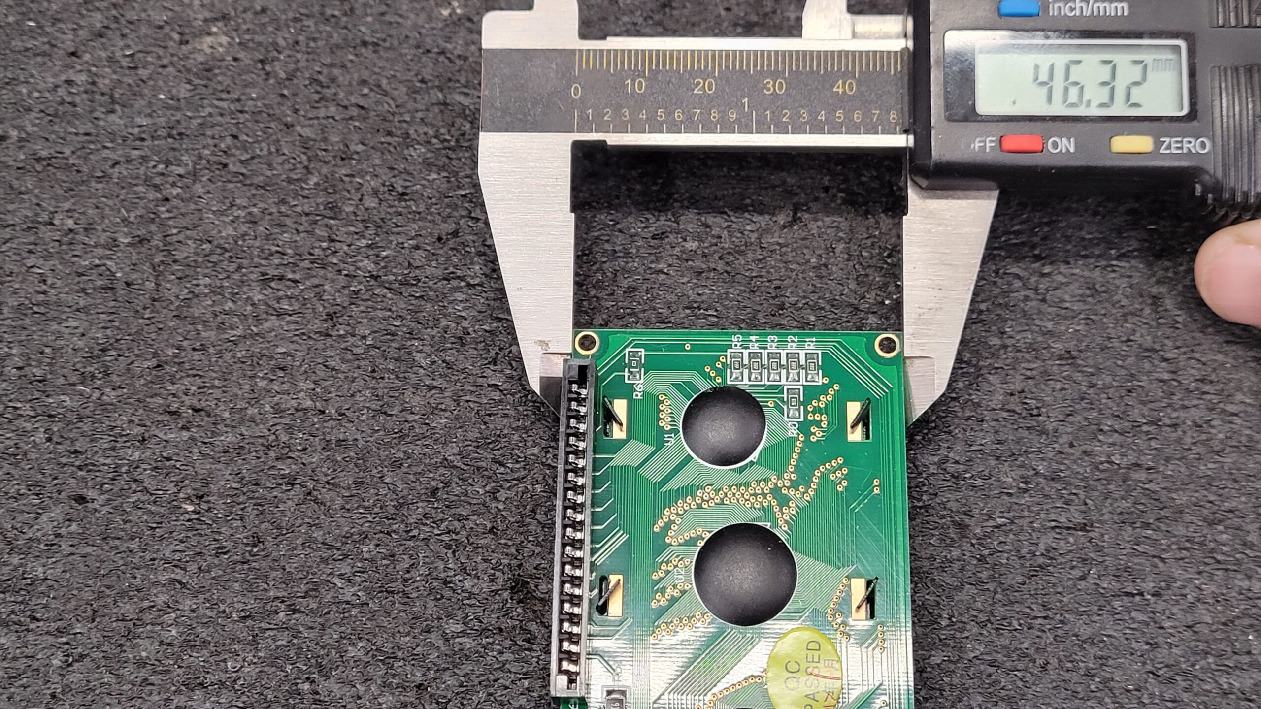
As we continue with the teardown of the Xeltek Superpro 7000, we come to the display board. This particular display board has the part number WYPCB177A and the model number WYM2004D, as indicated in the data sheet. Interestingly, it appears to be the same display used in the Superpro 6100N, with a 2004D 20X4 LCD that measures approximately 76-77mm x 46-47mm and features an FFC/FPC connector. During my investigation, I came across a compatible replacement display that I believe would work well as a replacement if ever needed.
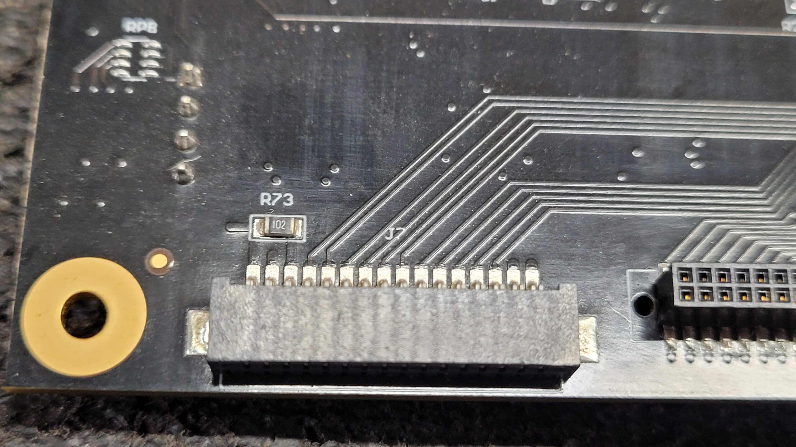
If your display contrast is off to bright or dim check R73 on the CPU Board By the Display Connector it should be 1K (102 or 1001) Pin 3 Right Side of Resistor Should be About 0.42 to 0.44V
The #PCBCake consists of 6 Interconnecting boards held in with 4 screws to the top cover.
Not sure what happened top the photos in this Xeltek Superpro 7000 Universal Programmer Teardown but looked good on my display when taken but look washed out on PC Screen. I am not a professional photographer! I think I need to invest in a real camera and learn to use it properly! Regardless here they are.
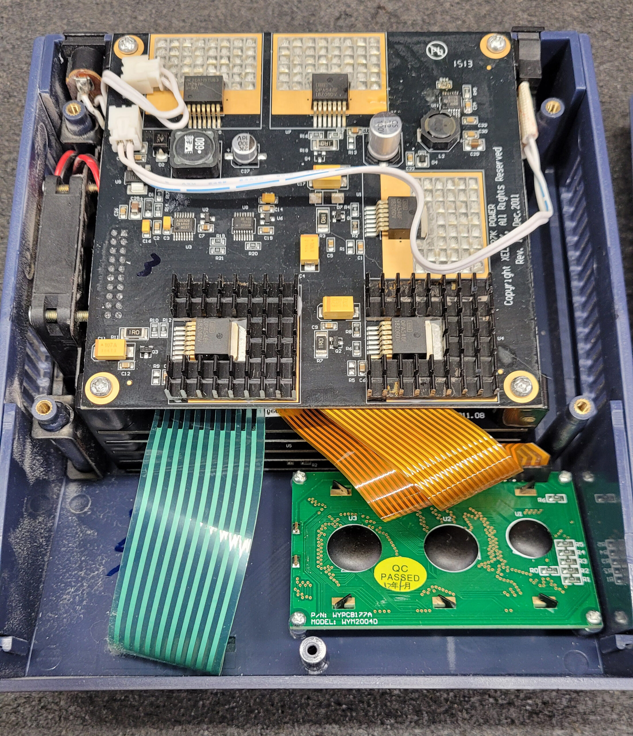
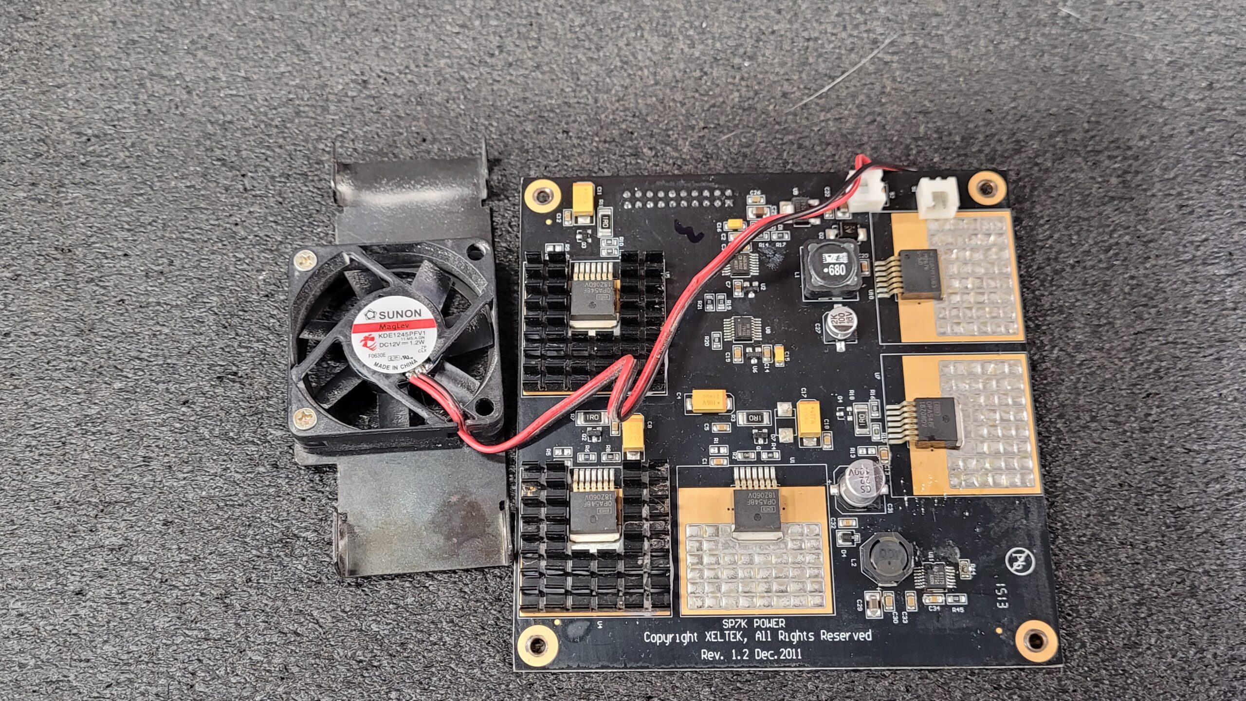
Power Supply Board Xeltek Superpro 7000 PN: SP7k PWR
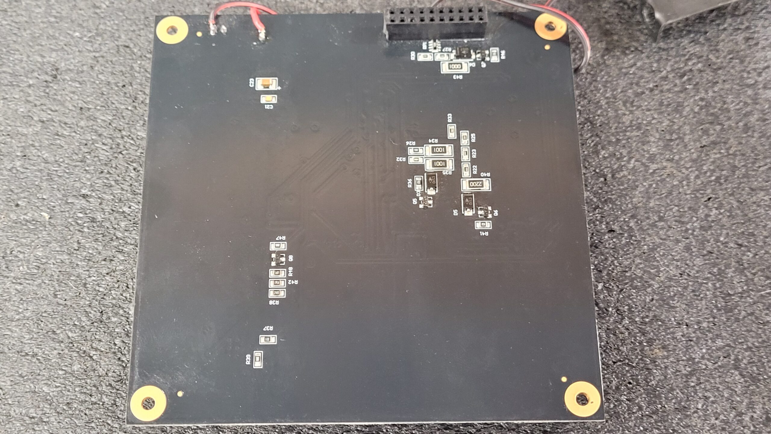
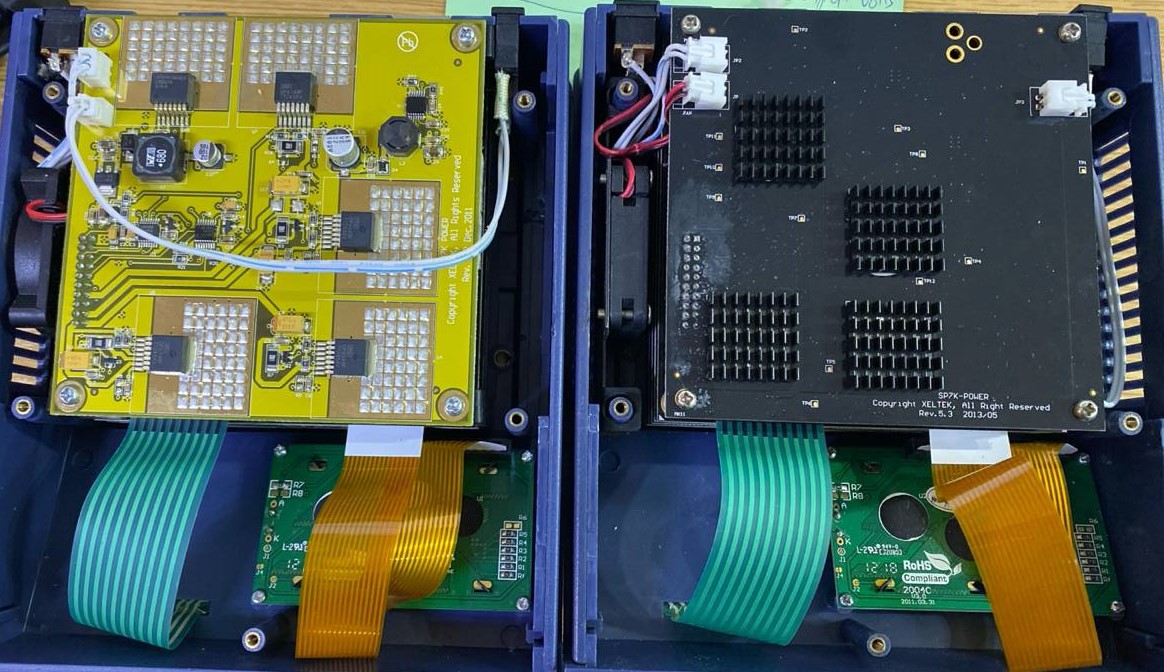
This Photo Courtesy of a Blog Reader. He has 2 Superpro 7000’s One has a Newer Power Supply Similar to that in the Superpro 7500.
Photos of His 7000 SP7K Power PCB Old Version but in a different color, with this color one can clearly see the traces which makes for simpler diagnostics.
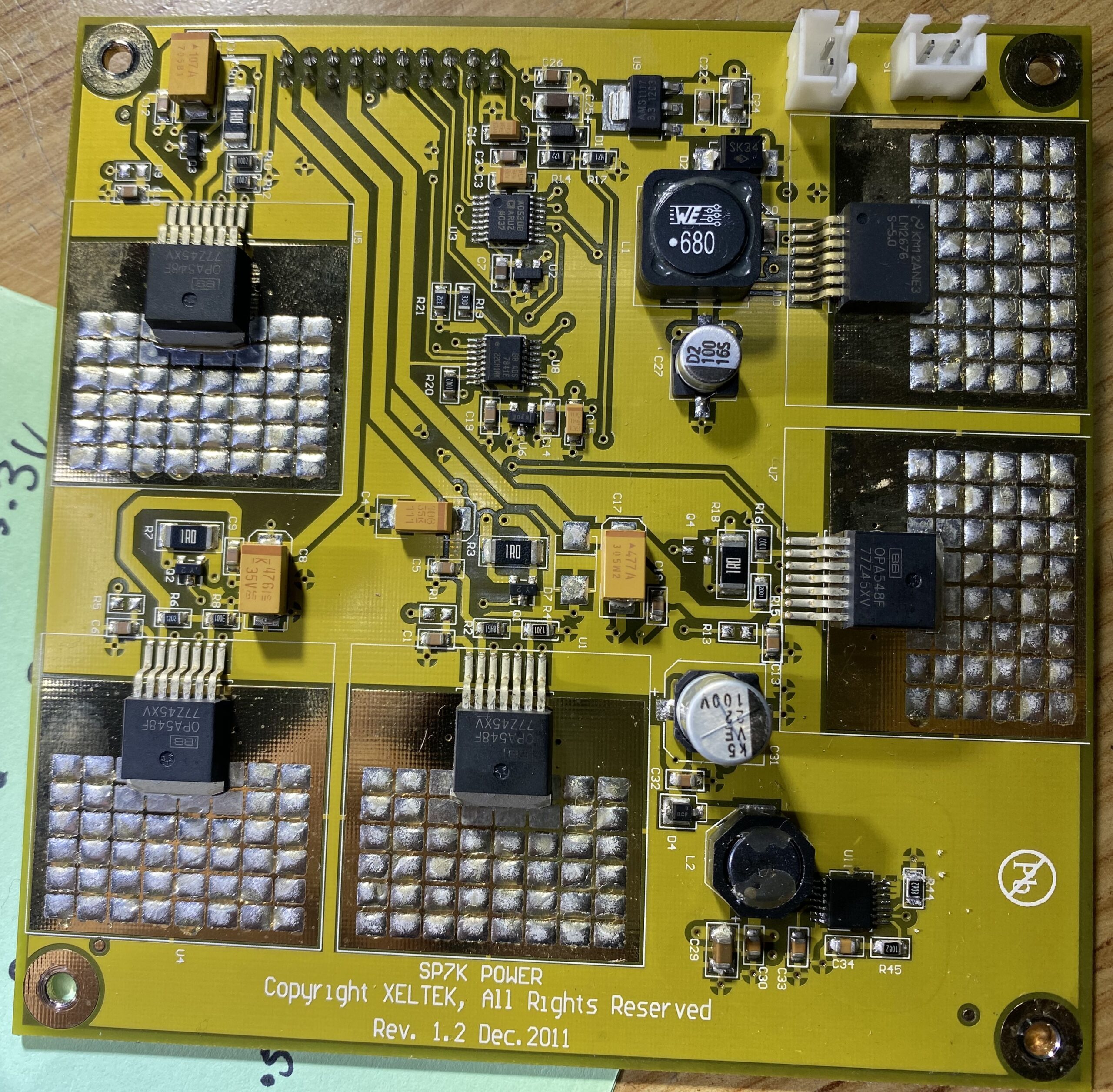
1 x LM2676 3A Step Down Regulator @ U10
4 x OPA548F High-Voltage High-Current Operational Amplifiers @ U1, U4, U5, U7
1 X TPS61175 3-A High-Voltage Boost Converter @ U11
1 X AD5308ARUZ 8 Bit Digital to Analog Converter @ U3
1 X ADS7841E Quad Channel Single Analog to Digital Converter @ U8
1 X AMS1117-3.3 Regulator @ U9
1 X REF3040AIDBZR (R30E) Voltage Reference 4.096V @ U6
1 X REF3033AIDBZR (R30D) Voltage Reference 3.3V @ U2
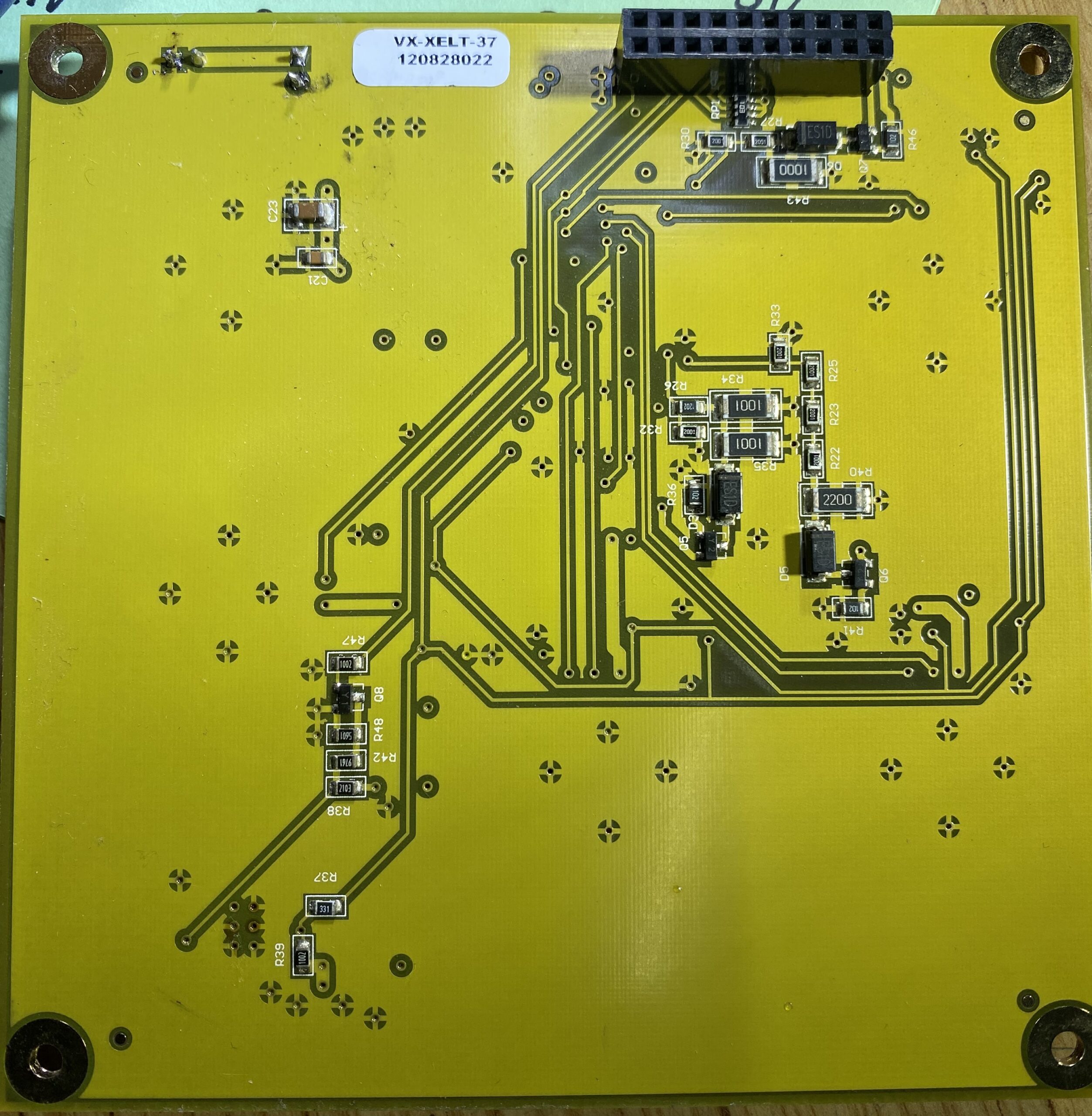
Voltages On 20pin Header After U11 Replacement.

Voltages and Pin Out I will format this better later just quick notes for now.
0.0V *1 | 3.3V Assume this is Pin 1 [*1 U3 Pin 1 LDAC]
0.0V | 3.3V
3.3V *2 | 0.0V U8 Pin 14 U3 * Pin 15 DIN Serial Data In [ *2 U3 P2 SYNC]
*3 | 3.3V U8 Pin 15 CS [**3 U8/U3 P16 SCLK]
GND | 0.0V U8 Pin 12 DOUT Serial Data Out
GND | 3.3V
GND | 3.3V U7
GND | 18V to C31 Form U11
5.0V | 0.5V V1
0.5V V3 | 0.5V V2
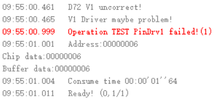
V1 is Supply For Pin Driver 1 V1 is Supplied Form U1 If you do a System Check PinDrv1 Failed it may be a shorted Transistor Q1
V2 Is Supply For Pin Driver 2 is Supplied Form U4 If you do a System Check PinDrv2 Failed it may be a shorted Transistor Q2

Note: If PinDrv1 and PinDrv2 have both failed Check U11
V3 Is Supply For Pin Driver 3 is Supplied Form U5 If you do a System Check Pin Driver3 Failed it may be a shorted Transistor Q1

U1 and U4 are Supplied Their Voltage Form U11
U5 and U7 are Supplied Their Voltage Form 12V DC In (Unsure what U7’s function is at this Time)
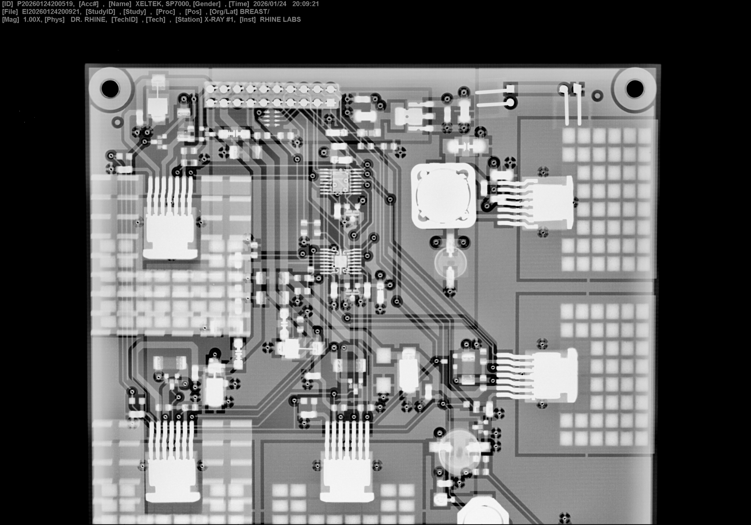
Update January 24th 2026
Here are Some X-rays of the SP7000 PSU Board I will Eventually Get to Taking X-Ray’s of the Board Entire Stack. Depending on the Donations X-ray Machines are not Cheep!!
If This Info Helps You, Help Me Bring You This Content. Cash App Project, and Appreciation Fund / or Just a TIP. Donate Here
The Board Exceeded my Sensor Size so I had to do 2 Images. I have not learned hot to scale and stitch 2 images together yet..

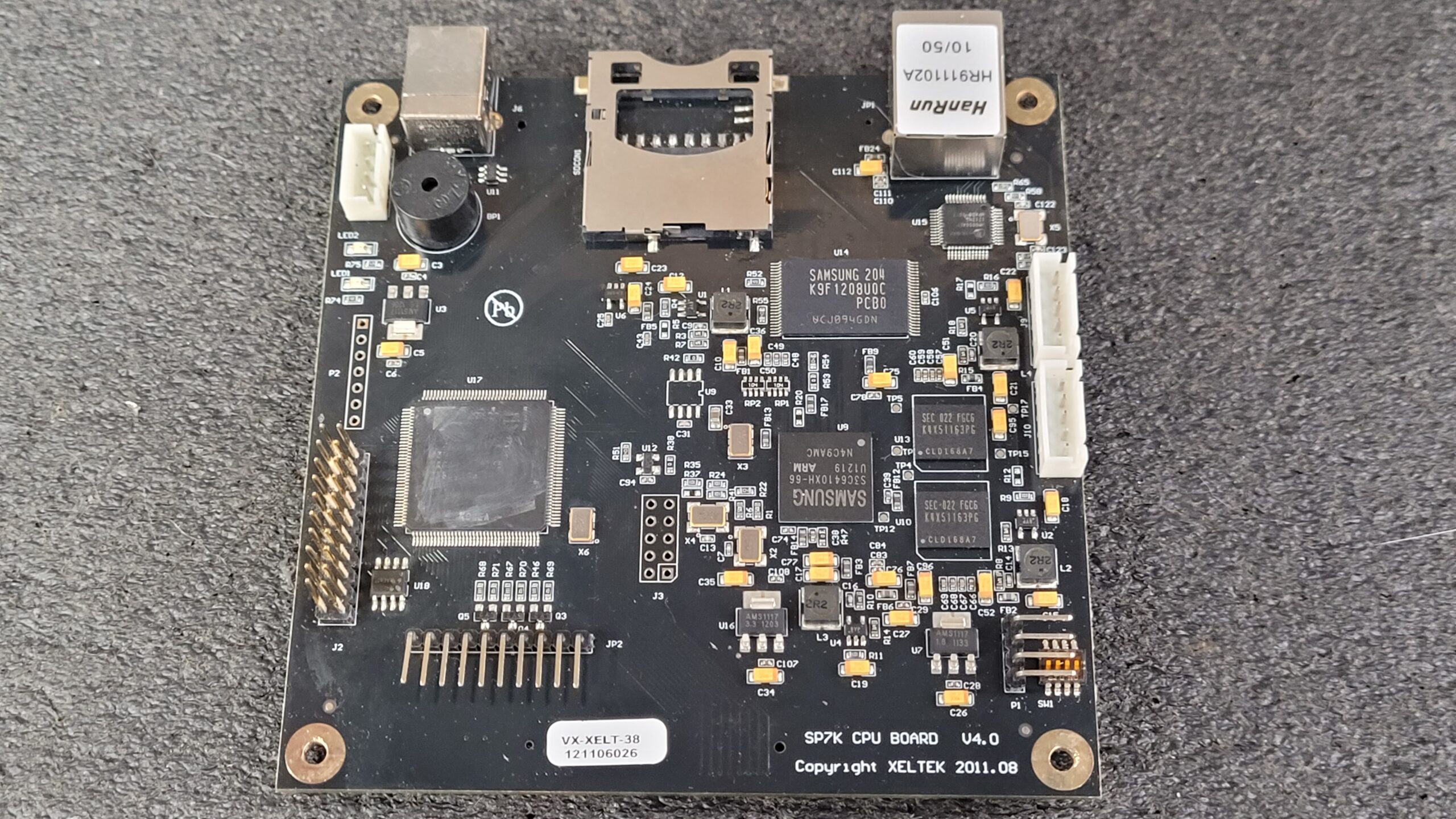
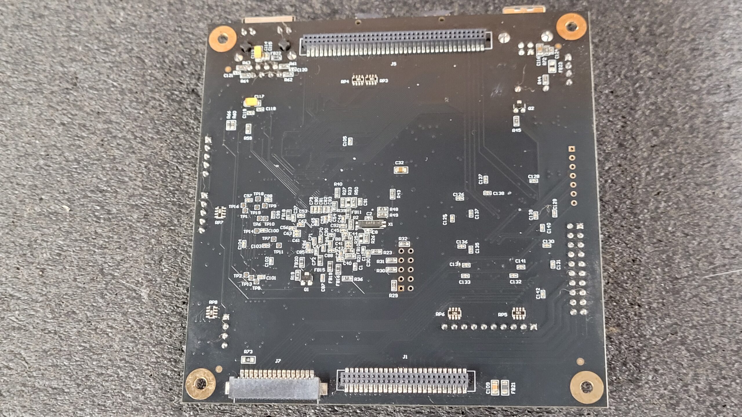
The Xeltek Superpro 7000 CPU board, PN SK7K CPU Board v4.0, has a ground off chip at U17, which makes it difficult to identify. However, it does have a Jtag header at J3, so I may revisit it another day and connect it to poke around.
From the datasheet, I learned that the scratched off chip at U17 in the TQ144 Package a ACTEL Proasic3 will either be an A3P060 or A3P125. The Superpro 7000 board is controlled by an S3C6410XH-66 ARM 11 processor at U9.
This CPU board features K9F1208U0C 64M x 8 bits NAND flash memory at U14 (datasheet), as well as two 512Mb DDR SDRAM chips K4X51163PI-FGC6 at U10 and U13 (datasheet). Additionally, it has a DAVICOM DM9000AEP Ethernet controller(datasheet), with a Xeltek AE801 chip at U18.
Wondering how useful a SMDK6410 development board datasheet / schematic would be for basic info.
I’m curious about the P1 header (Serial/UART?) and the P2 header (JTAG?) and J3 on the board, as well as the purpose of J9 and J10. I was told at one point that these Superpro Programmers run a form of embedded Linux. Maybe I should request the source code (just kidding! or am I?)
Update 08/29/2023 P1 Is Serial/Uart 115200 bps (8-N-1) I Hooked it up to a serial Port Pins 1 tx (Y) and 3 rx (O),
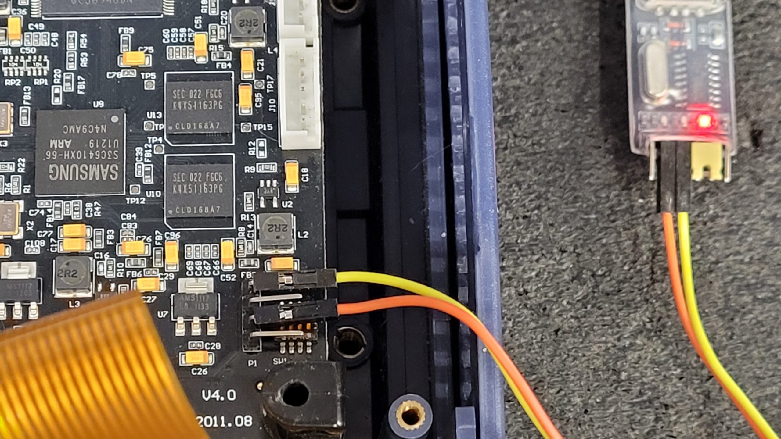
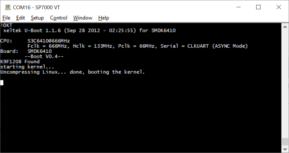
When hooked to a basic terminal this is what is displayed. I think it is missing some data. I will work on it.
!OKT
xeltek U-Boot 1.1.6 (Sep 28 2012 – 02:25:55) for SMDK6410
CPU: S3C6410@666MHz
Fclk = 666MHz, Hclk = 133MHz, Pclk = 66MHz, Serial = CLKUART (ASYNC Mode)
Board: SMDK6410
–Boot V0.4–
K9F1208 Found
starting kernel…
Uncompressing Linux… done, booting the kernel.
Programmer Is Runing, Linux version 2.6.34.7
Full Log Dated 07/11/2024
Xeltek Superpro 7000 Uart Linux Linux version 2.6.34.7 07-11-2024
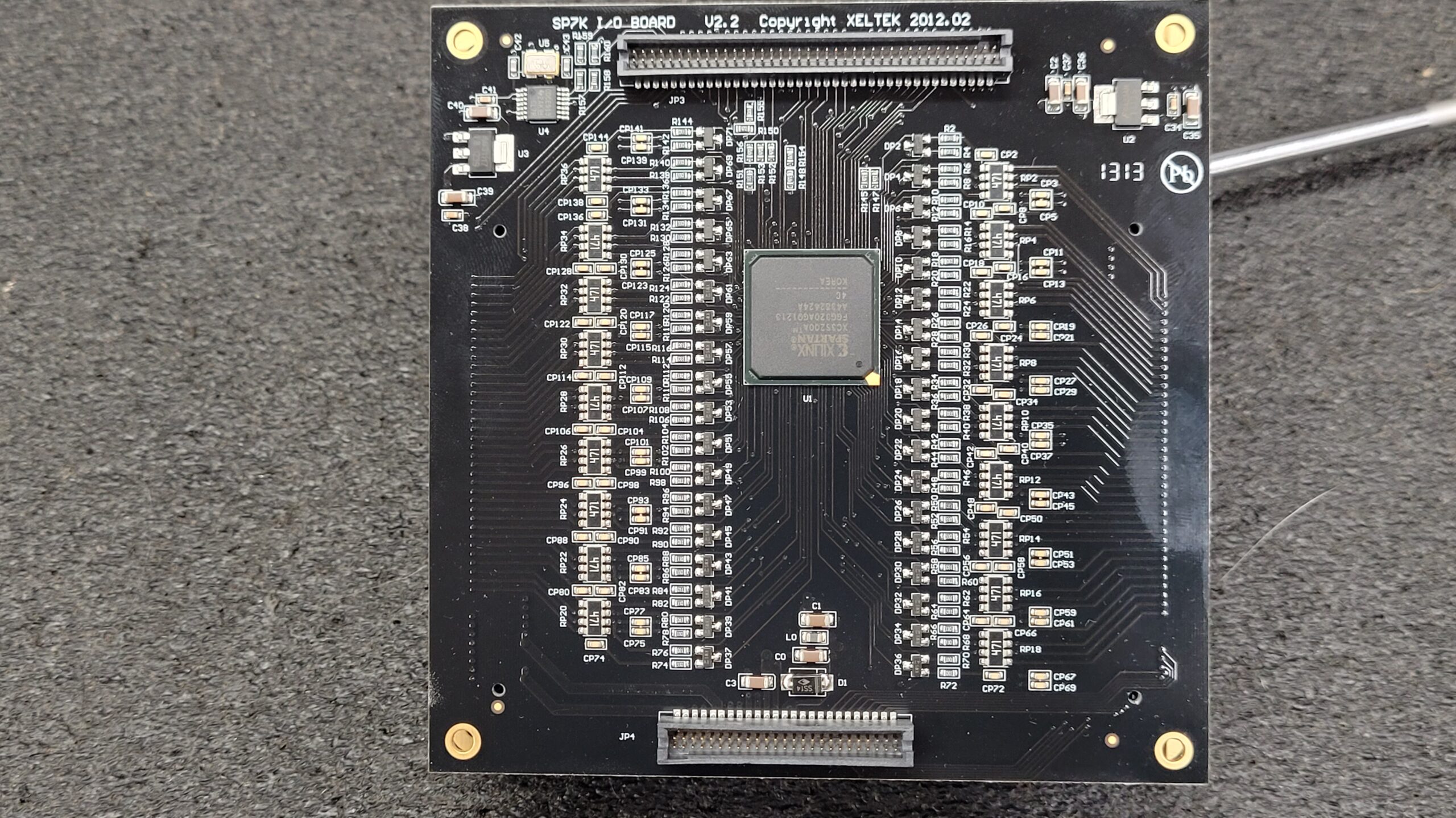
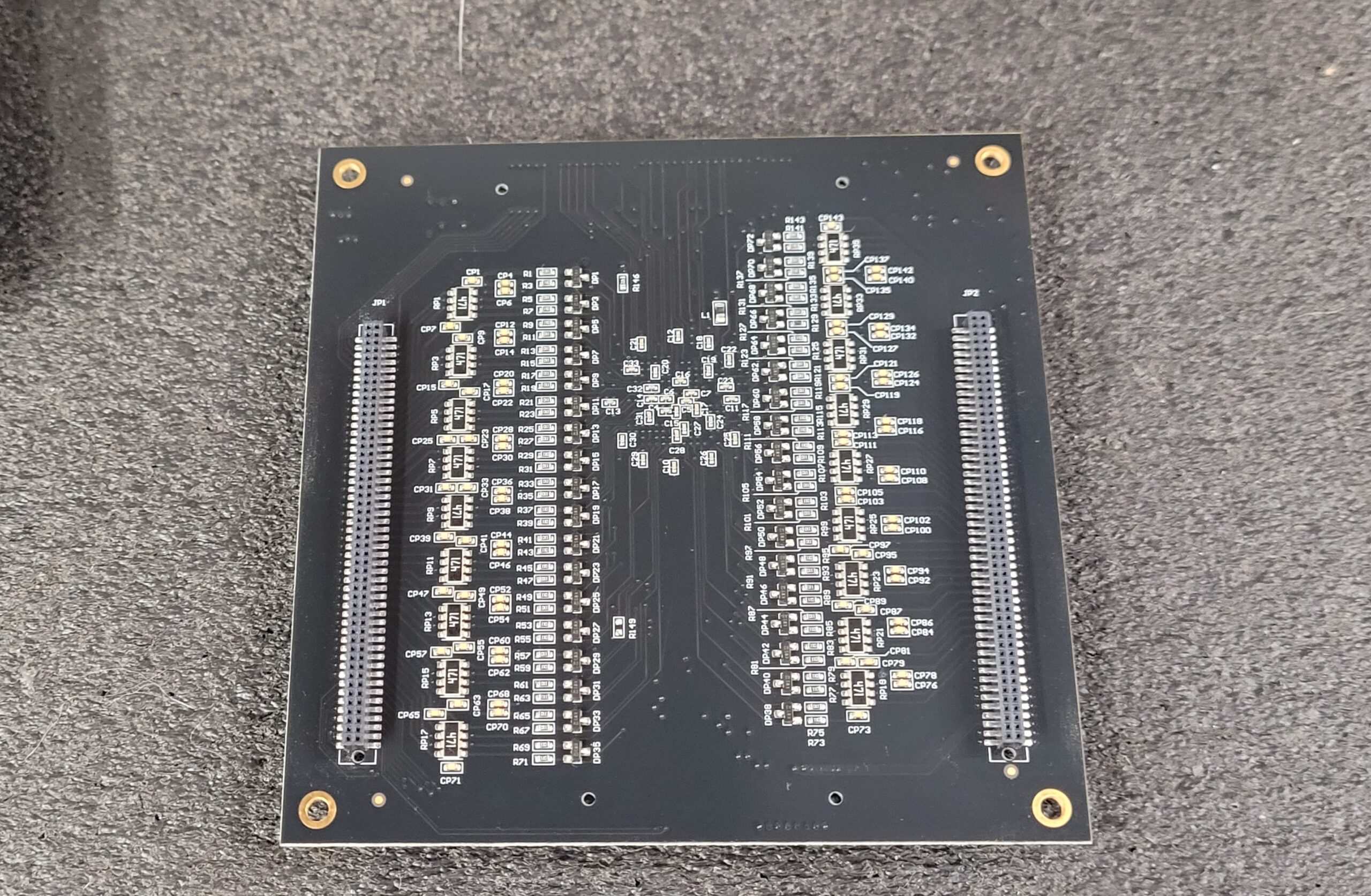
I/O Board
Playing with A SP7000’s July 2024 It Seems The IO Board is Paired to the CPU Board Swapping them Gives ERR:2000
INVALID SN! All the other boards can be swapped out and exchanged between programmers.

Some Noteworthy Parts On the I/O Board.
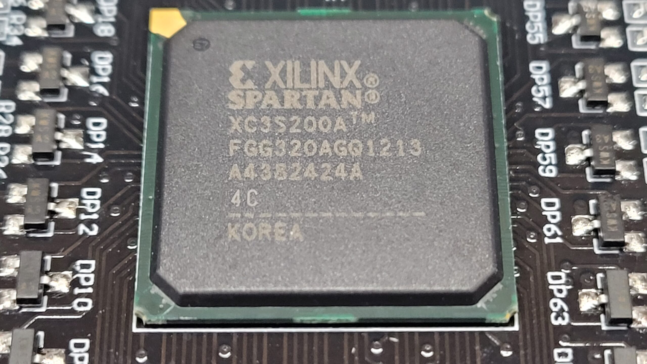
U1 Xilinx Spartan 3 FPGA XC3S200A (Dataheet)
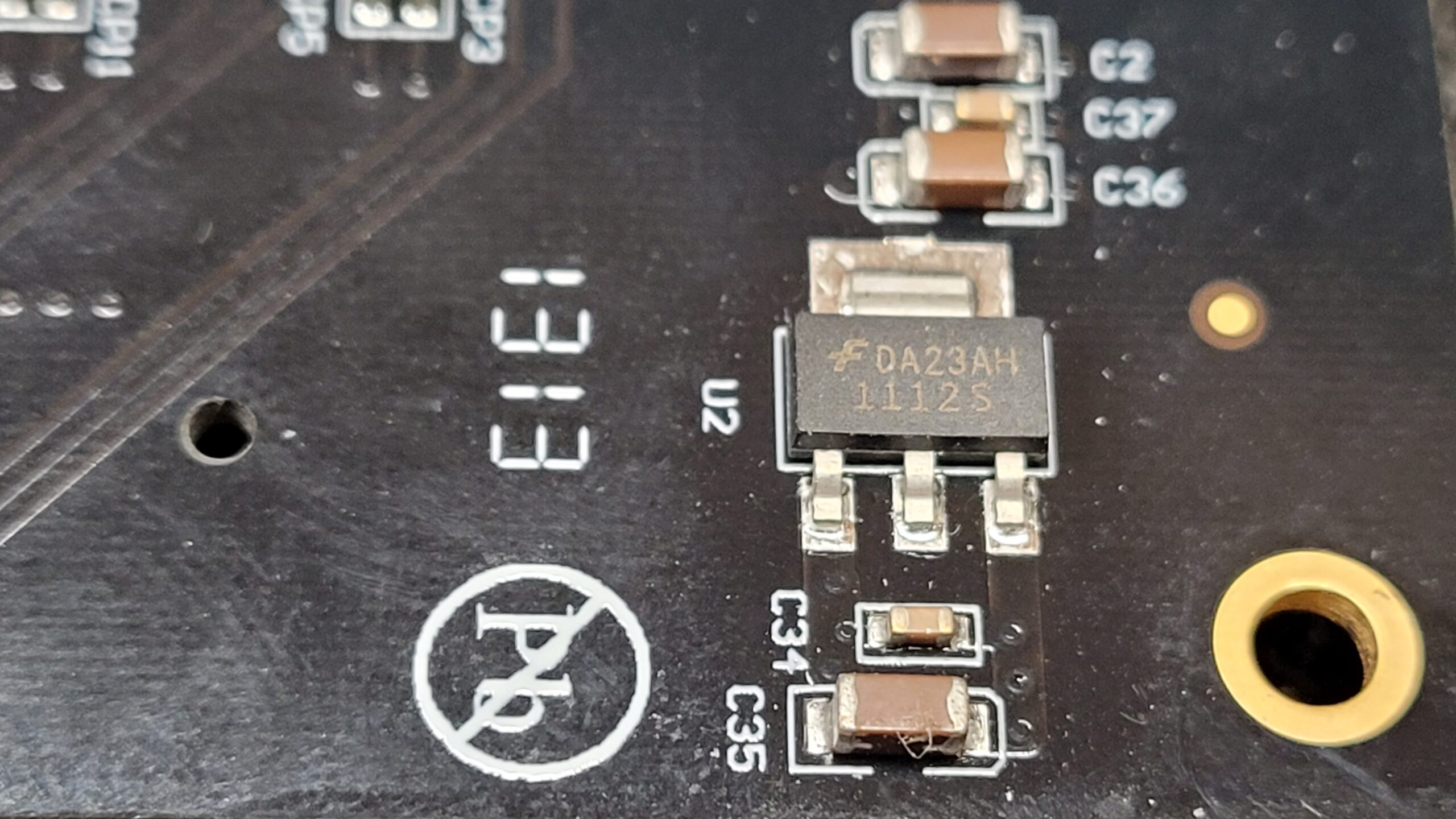
U2 DA23AH1112S (Unknown)
U3 AMS1117 1.8V Regulator
U4 CDCE913 Low Power LVCMOS Clock Generator
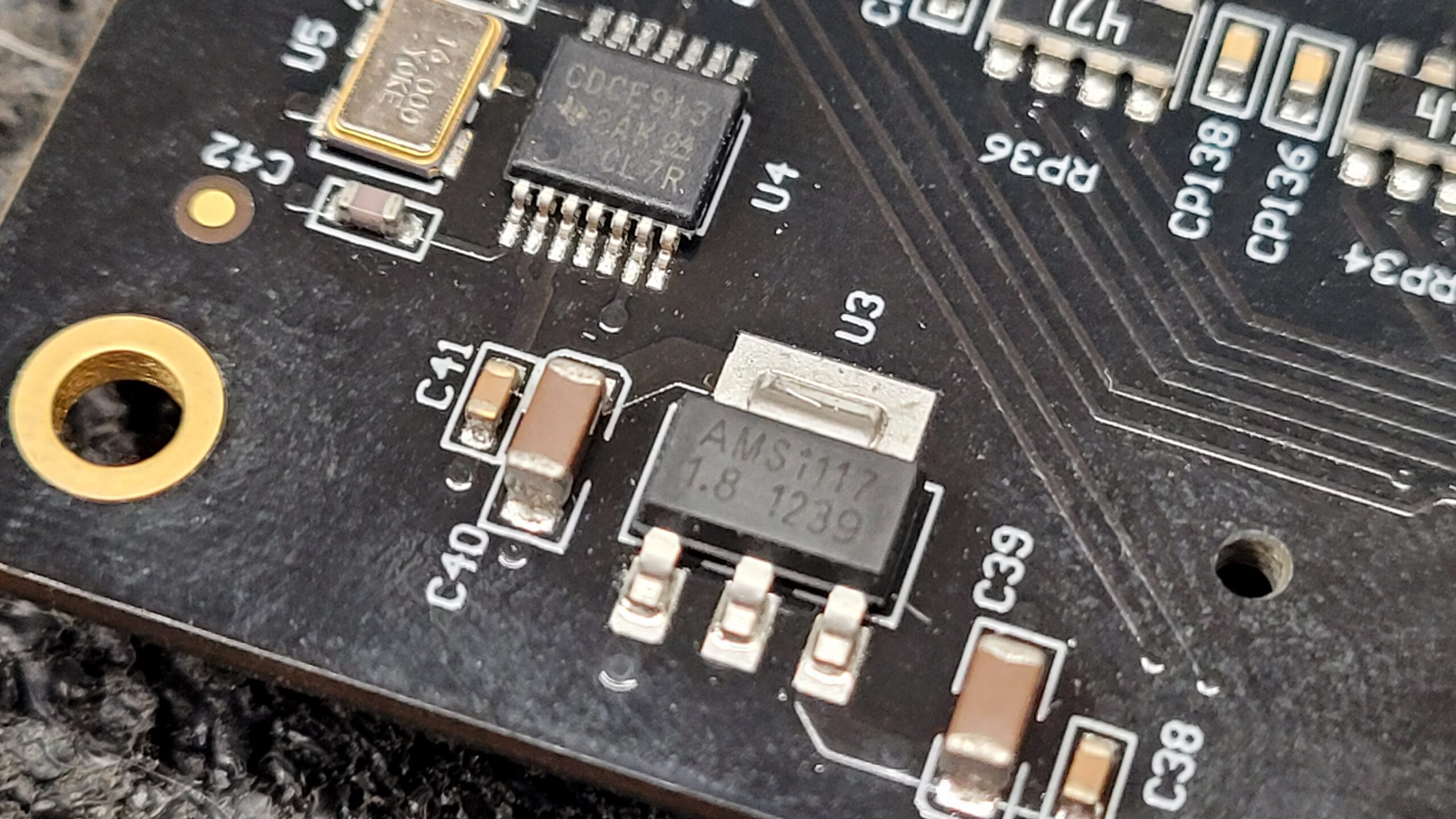
DP1-DP144 A3 1SS181 Diodes
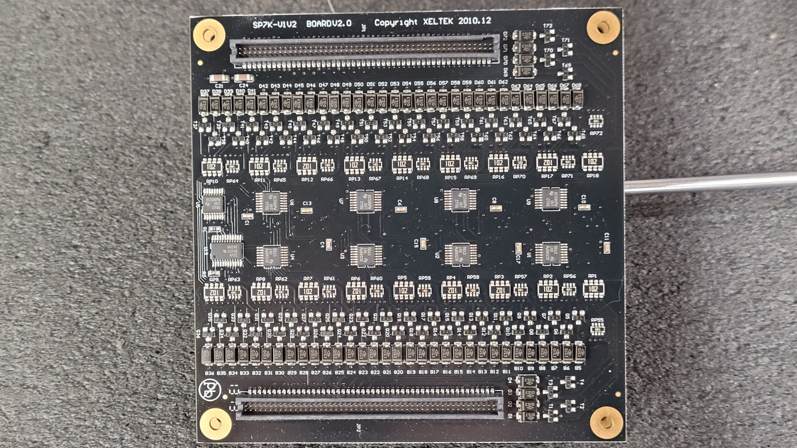
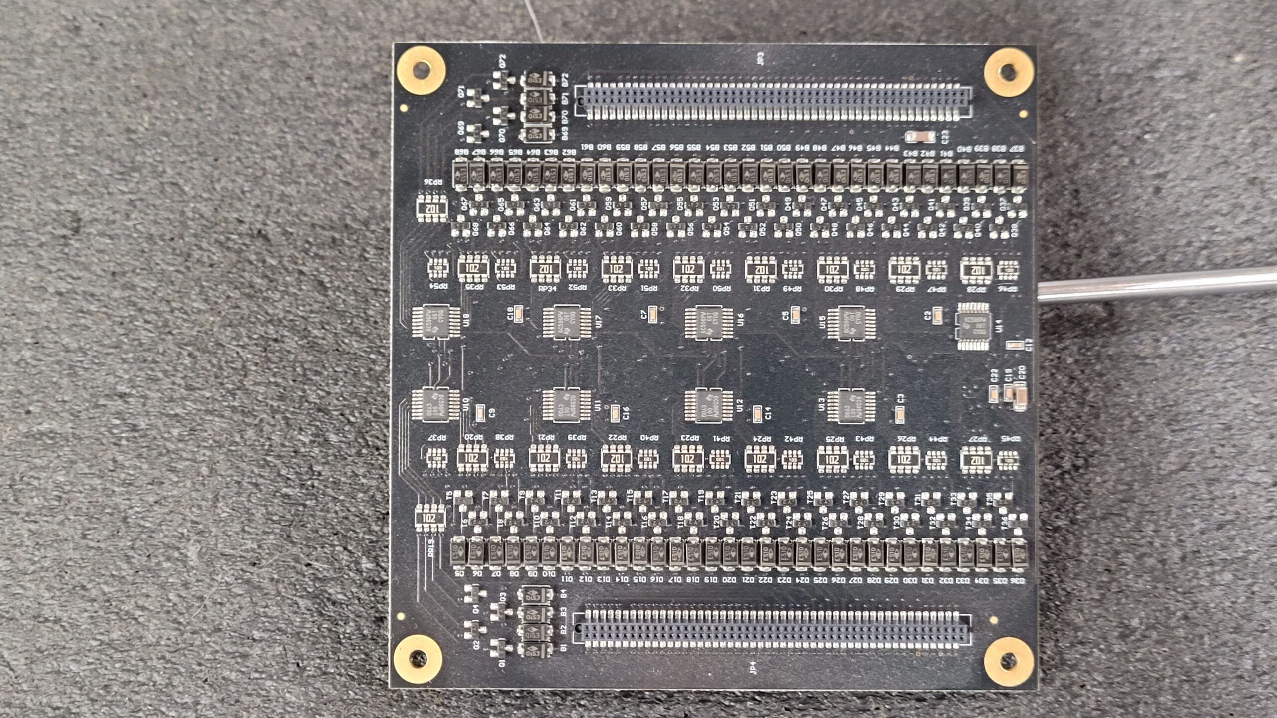
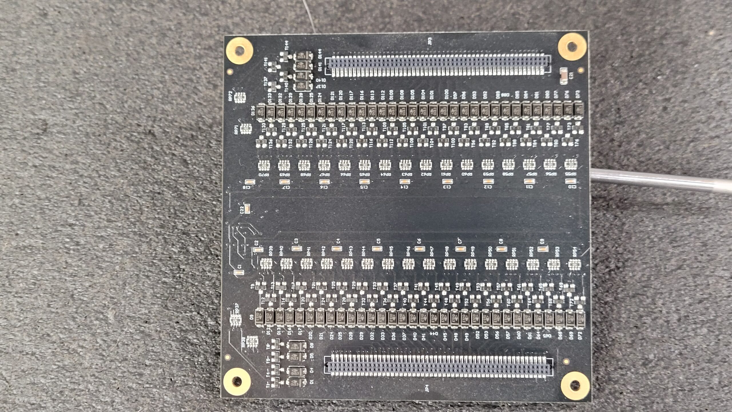
SP7K-V1V2 Board For Xeltek Superpro 7000 a lot of 6C596PW Shift Registers & Diodes. Then you have Y2 a SOT package SS8550 transistor?
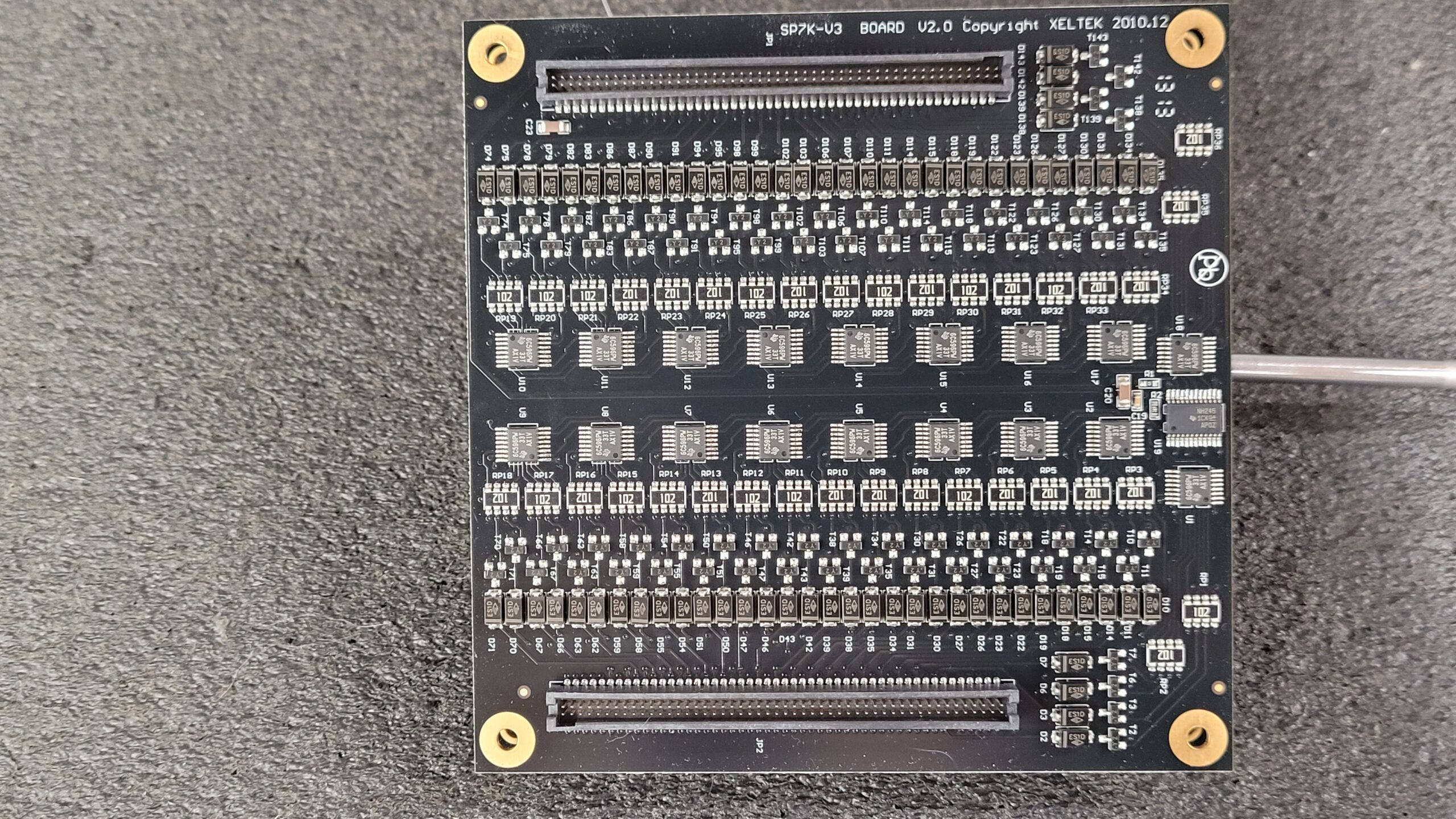
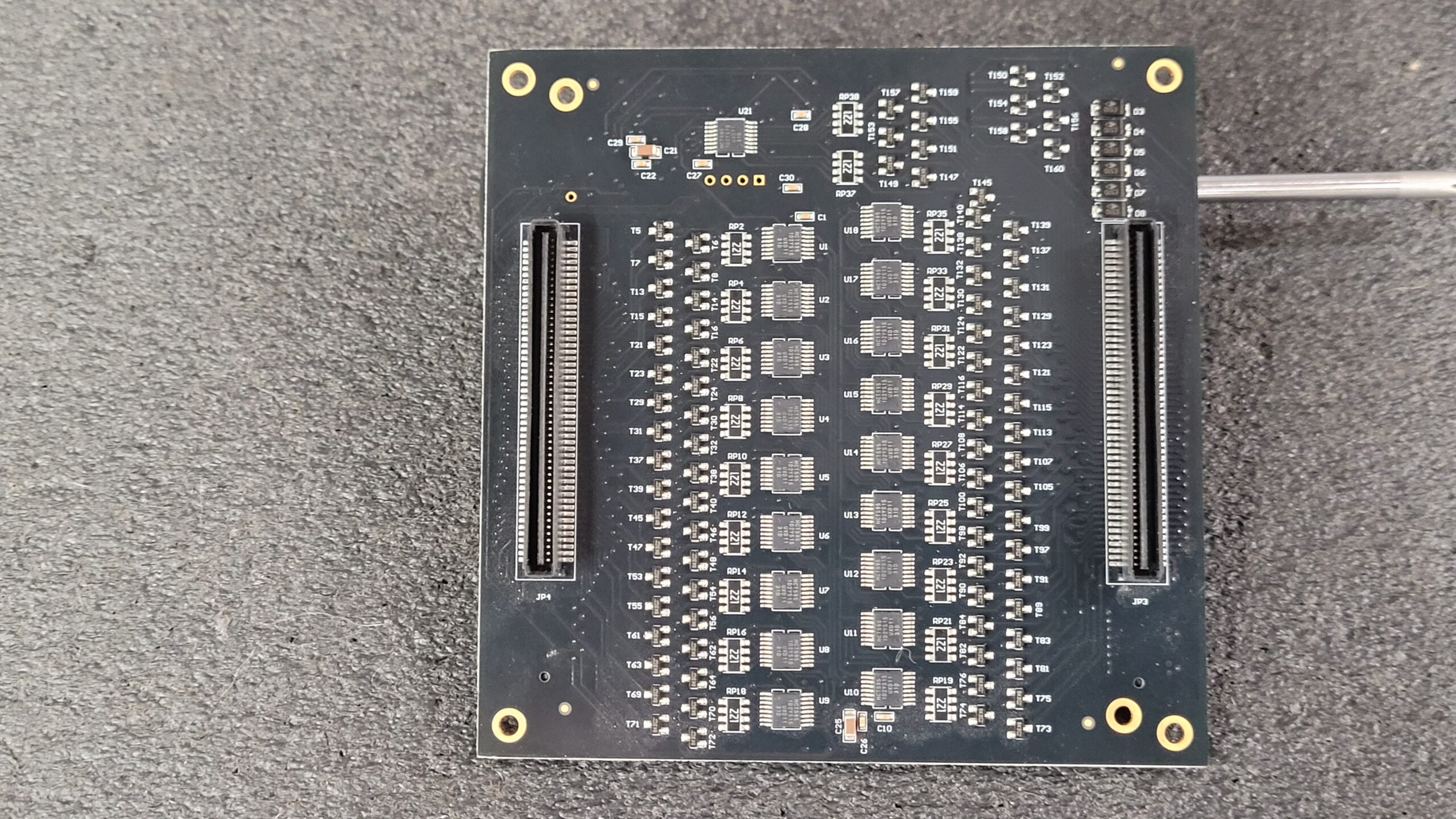
Board Part SK7K -V3 For Xeltek Superpro 7000 the NH245’s I believe is a SN74LVC8T245 8-Bit Dual-Supply Bus Transceiver.
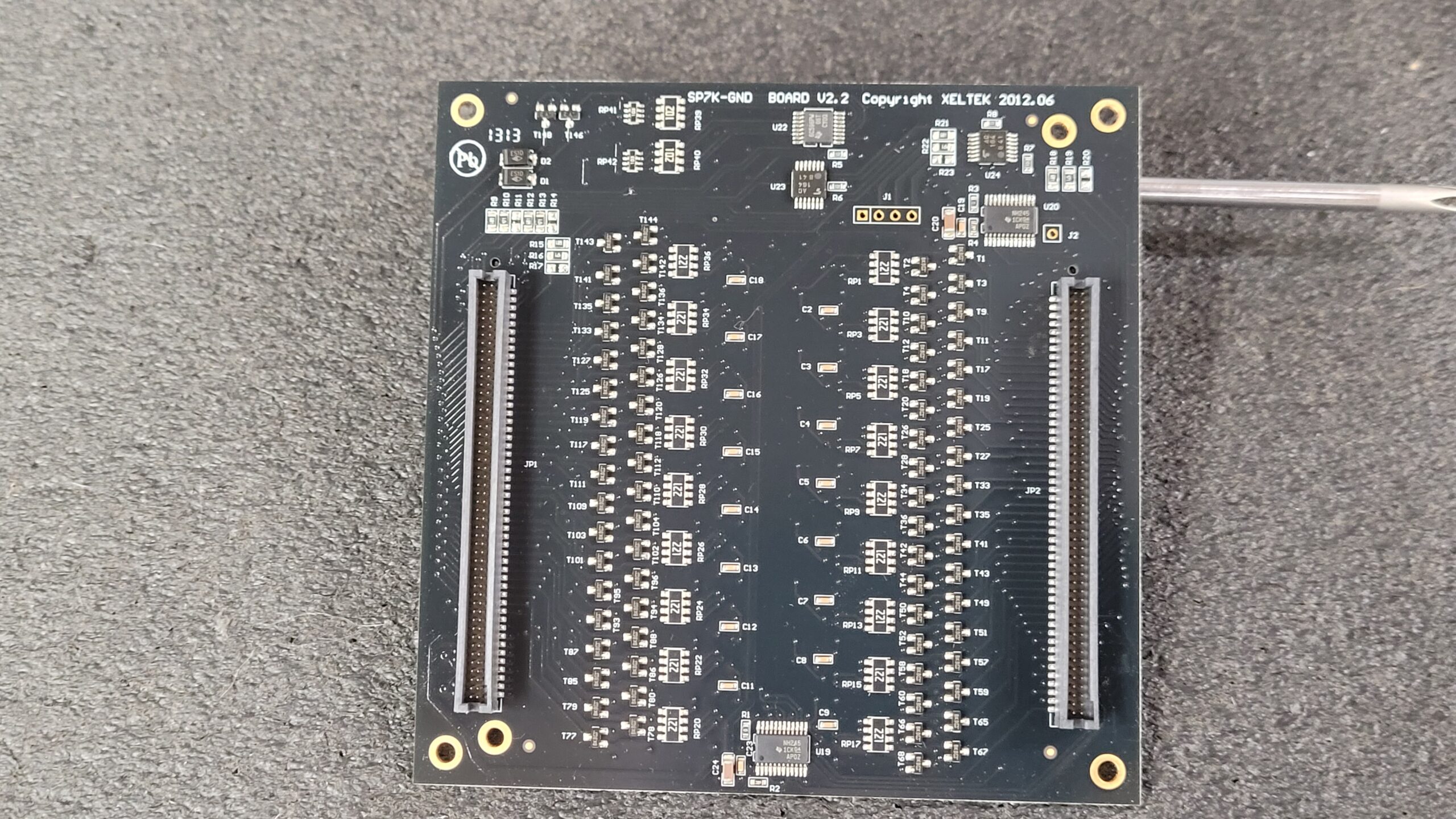
Ground Board Xeltek Superpro 7000 SP7k-GND HCT595 Chips Data Sheet Transistors have marking BKD Assume they are KTC8050S-D Bipolar Transistors
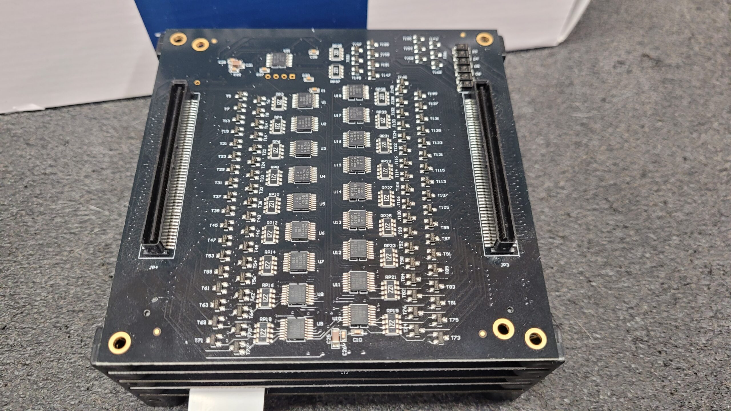
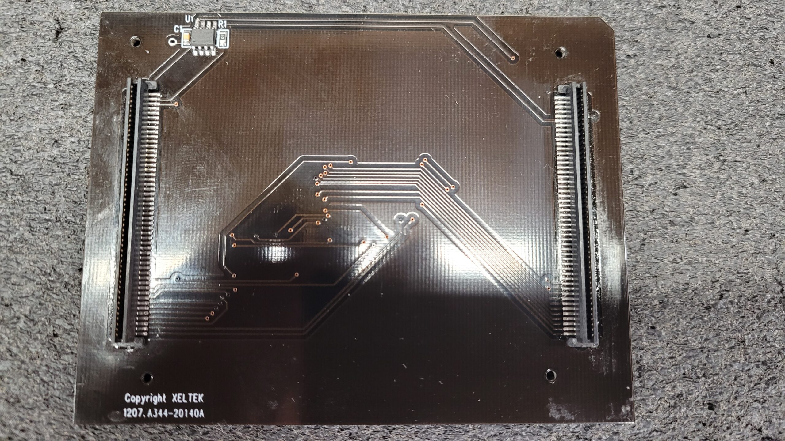
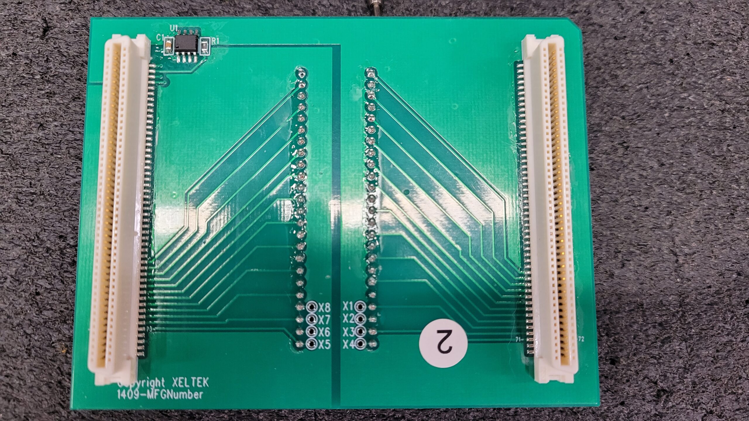
SP7K Stack a little bit clearer on the bottom side! The board to board connector on top is an Oupiin 2349-100G00DN1T
After examining the power supply board more closely, it became clear that the soldering on U11 was very poor, with pry marks on the chip and a noticeable gouge near C34 on the circuit board. As a result, I decided to remove U11 to get a better look. It was clear that there had been a botched repair attempt at some point, as the pads had been lifted and the chip had not been properly soldered down.
Dealing with this kind of issue is always frustrating, and the thick black solder mask on this particular board made it even more difficult to work with. However, with some patience and careful attention to detail, I was able to address the problem and get the board back in working order. In the end, it’s always satisfying to overcome these challenges and bring a piece of equipment back to life.
Before reassembling the programmer, I took the time to clean up the flux a bit. However, it’s clear that a more thorough cleaning is necessary. In fact, I think it would be best to give the board a quick dip in the ultrasonic cleaner for a few seconds to ensure that it’s completely free of any residual contaminants.
Hope this Xeltek Superpro 7000 Teardown helps someone. This is a living blog and I will update as time allows.
I do not have a EX0001 Adapter and Seems that Xeltek has Discontinued them. So this will have to stay on the back burner till another day.
Update, 07/2023 The Xeltek Superpro 7000 EX Adapter’s Uses a Uncommon Oupiin 2348-100G00DP1T
On the modern Xeltek GX Adapter it Uses a Common Avery Roust Hirose FX2-100S-1.27SV(71)
Here is a EX0001
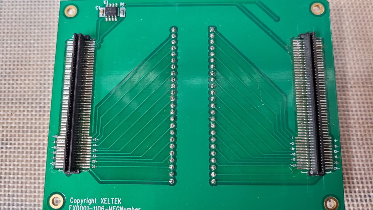
According to information provided by Xeltek China, it has been stated with that the EX and GX adapters employ compatible security chips, thus indicating a high likelihood of compatibility between the two. It is worth considering the potential creation of an adapter that bridges the uncommon Oupiin connector with the Hirose connector. However, it is important to note that a definitive decision has not been reached on whether this adapter will be produced, thereby emphasizing the need for further evaluation and deliberation.
I have 3d Printed a Socket Cover for the Xeltek Superpro EX Adapter.
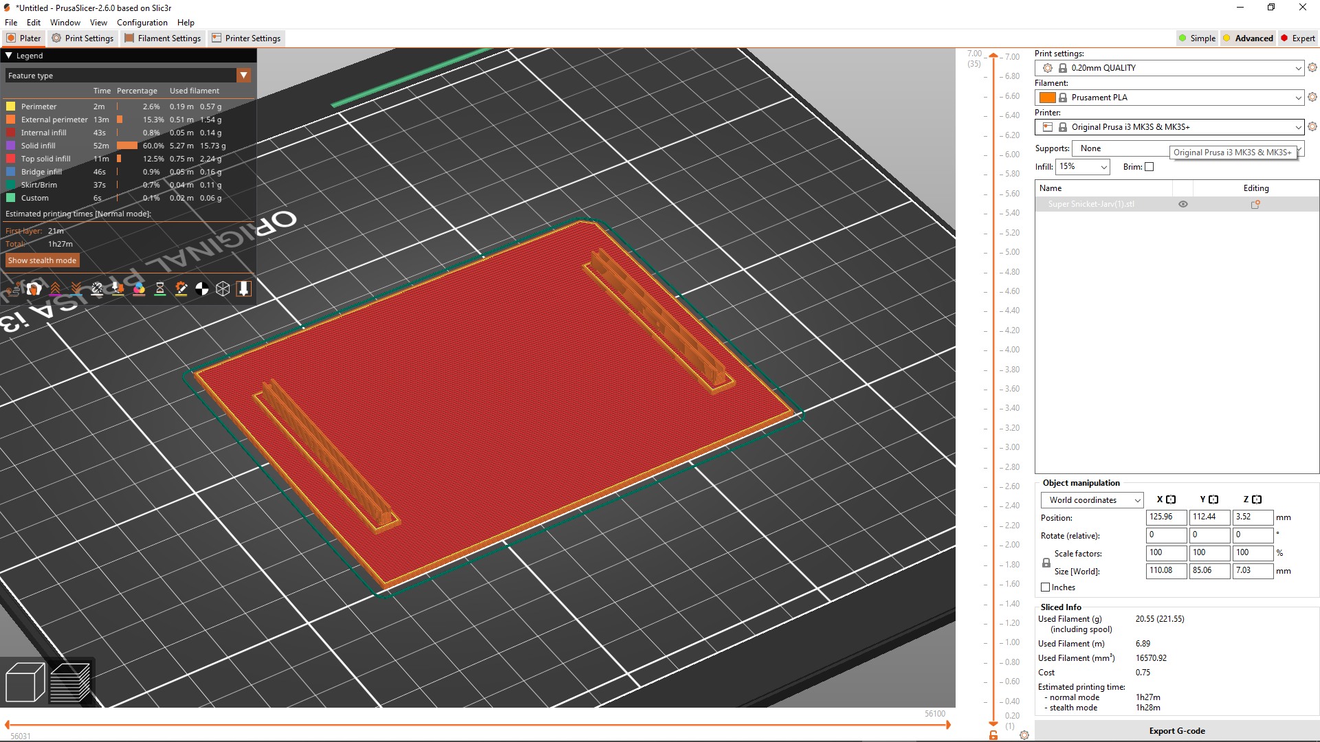
Here is the 3D Printed Cover. I will release the STL File On My Printable Profile As I Did with the Superpro 5000-6100N’s Check Back Here or my Printable’s Profile Regularly.
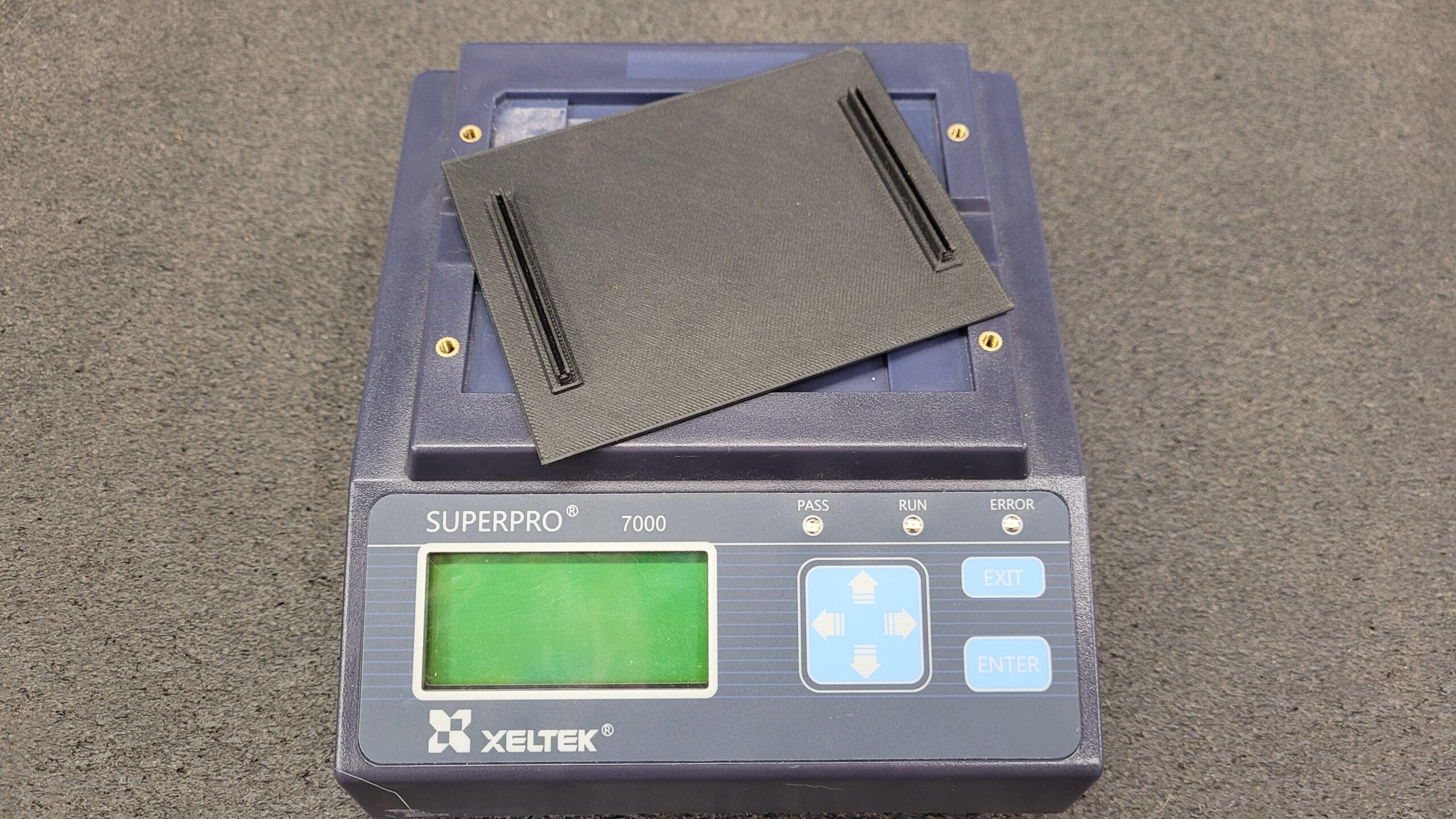
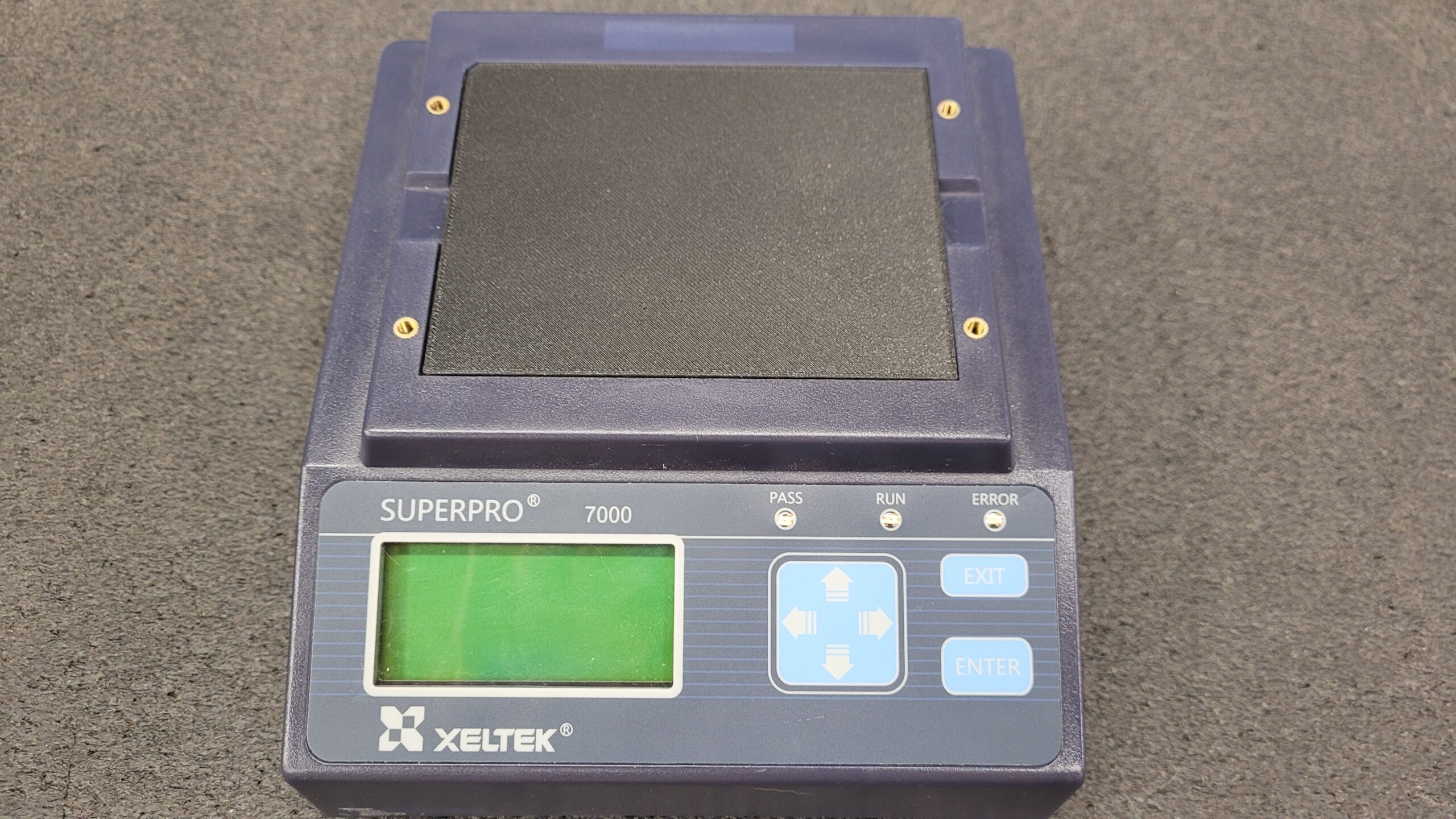
01/26/2024 After a Long Wait I Finally Found a Xeltek EX0001 Adapter For the Superpro 7000.
The Test..
It seems the replacement of the TPS61175 allows it to work.
A Bonus, The Magic Chip For 7500 works for the Superpro 7000 Also.
Update, February 4th 2024, Since Xeltek discontinued the Superpro 7000 EX Adapters a few years ago. I have been informed that the 7500 GX Adapters AE801 Chips are interchangeable with the 7000 series. I verified this with the Magic Chip entered in a GXXXX and the 7000 had no issues, I also swapped a genuine GX chip to the EX and it had no issues. So, To address this shortage, I am developing and EX to GX Converter Adapter for the Xeltek Superpro 7000, enabling the use of GX Adapters on the discontinued Superpro 7000 model a bonus when you upgrade to the 7500 your GX adapters can still be used.
See Post On the EX to GX Adapter Project: https://www.stevenrhine.com/?p=133519
Xeltek China / USA
Right to Repair Score: D (They Will Repair But Costs More then Item Is Worth)
Check Out My Xeltek Superpro 7500 Universal Programmer Post.
Last Updated on January 24, 2026 by Steven Rhine
[…] Source based on an Atmel Tiny25 chip. Furthermore, I invite you to take a look at my post on the Xeltek Superpro 7500 Universal Programmer, where I discuss my additional dealings with […]
[…] Looking for the Xeltek Superpro 7000 Teardown Click Here. […]
[…] Display seems to be the same display as the Xeltek Superpro 5000-6100N and Xeltek Superpro 7000 WYM2004D / WYPCB117A Flip the Unit on its Back and The Circuit Board Stack Assembly will lift […]
[…] to do this is at the Large 100V Electrolytic Capacitor C31. You can get a list of voltage s on the Superpro 7000 Teardown Post. If you are Missing 18V That means U11 on the Power Supply is most likely fried. If you have other […]
[…] Off Chip.. Just a little bit of IPA and is Revealed an Actel A3P060-VQG100 FPGA Same FPGA in the Xeltek Superpro 7000 and Xeltek Superpro […]